The RACE RESULT Decoder receives the signals from the transponders using antennas, then calculates and saves the final detection time, based on a very precise clock and the transponders’ signal strength when crossing the timing line.
It provides these passings (bib number, time, and additional information) to the scoring software such as RACE RESULT 12 or uploads the data directly to an Internet server.
The decoder does not perform further calculations such as calculating the net time, lap times, etc. All this will be done by your scoring software.
It also guarantees uninterrupted operation as it runs independently from a computer and external power supply. All passings information is automatically stored on the device.
Safety and Regulations
General Safety Responsibilities
This unit has been designed and tested in accordance with the CE Certificate of Conformity and has left the manufacturer's plant in condition, fully complying with safety standards.
To maintain this condition and to ensure safe operation, the user must observe all instructions and warnings given in this operating manual.
Applicable local and national safety regulations and rules for the prevention of accidents must be observed in all work performed.
FCC/IC Statement
Changes or modifications not expressly approved by the party responsible for compliance could void the user's authority to operate the equipment.
This device complies with Part 15 of the FCC Rules and with Industry Canada license-exempt RSS standard(s). Operation is subject to the following two conditions: (1) this device may not cause harmful interference, and (2) this device must accept any interference received, including interference that may cause undesired operation.
Le présent appareil est conforme aux CNR d'Industrie Canada applicables aux appareils radio exempts de licence. L'exploitation est autorisée aux deux conditions suivantes : (1) l'appareil ne doit pas produire de brouillage, et (2) l'utilisateur de l'appareil doit accepter tout brouillage radioélectrique subi, même si le brouillage est susceptible d'en compromettre le fonctionnement.
Warnings and Cautions
The following alerts are used in this manual:
- WARNINGS alert users of potentially dangerous situations.
- CAUTIONS alert users of potential equipment damage.
Warnings and cautions are indicated by:
- the text WARNING or CAUTION,
- a description explaining the hazard and how to avoid it,
- an icon:

Where to Operate the System
UHF operates globally on different frequencies (e.g. Europe 865 - 868 MHz, USA 902-968 MHz, AUS 920-925 MHz) with different detailed regulatory requirements. That is why RACE RESULT provides different versions of the system for different regulatory areas. When operating the passive part of the system in another country, make sure it complies with local regulation.
The RACE RESULT Active System uses universal frequencies that can be used globally.
Decoder Elements
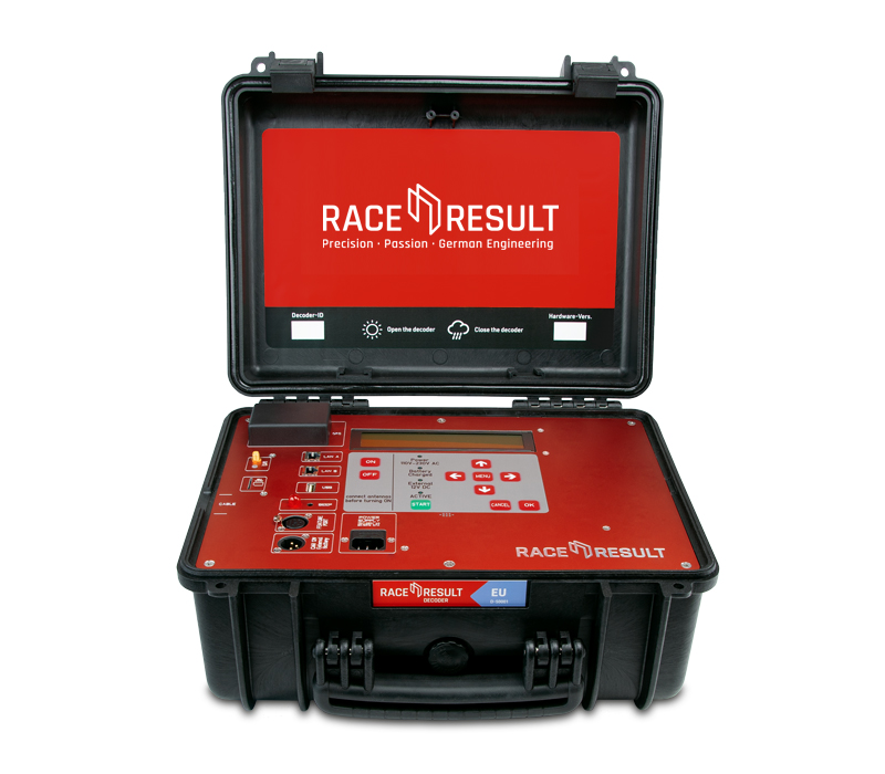
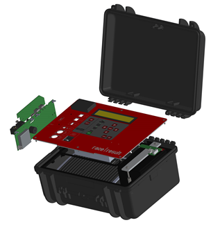
Case
The electronics of the RACE RESULT decoder are integrated into a solid hard case. Because of the connectors on the front panel, the front panel is not water-proof. Therefore please note:
 During rain, the lid of the decoder must be closed and locked. Therefore, all cables have to be led through the slot between front panel and lid on the side.
When operating the system during hot temperatures (>25°C / 80°F) and located in direct sunlight, the lid should be opened. Otherwise, the system may perform a temperature triggered emergency shutdown.
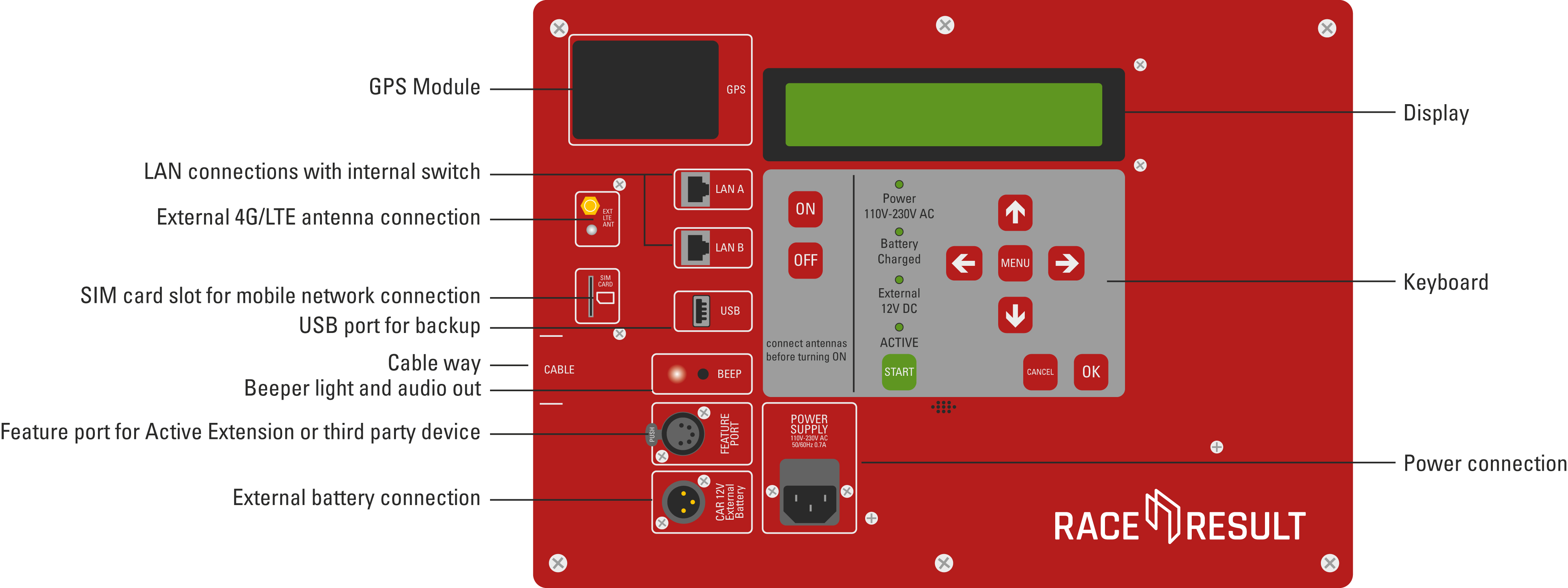
Connectors
The decoder box has the following connectors on the front panel:
|
Power |
Power supply, 110-240V AC, 50/60Hz. |
|
External Battery |
Using the enclosed cable, the decoder can be connected to an external battery or a cigarette lighter of a car (see External Battery Port). |
|
Ethernet |
The detections can be read through a network connection (see Ethernet Connection). |
|
USB |
Using the USB port, the detections can be saved on a USB stick (see USB Connection). |
|
Audio |
The decoder contains an internal beeper, which will give an acoustic signal on each detection. Alternatively, you can connect an external speaker or headphones. The internal beeper will then be turned off. |
|
Feature Port |
The Feature Port serves to connect additional accessories, including the Active Loop (see Feature Port). |
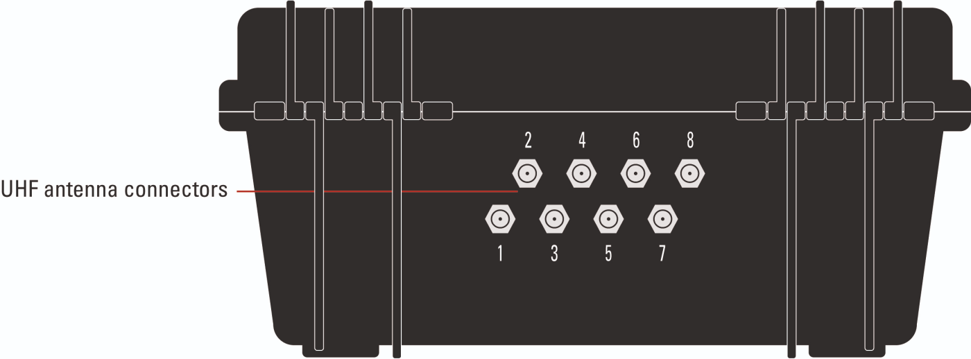
Additionally, the decoder box has 8 antenna connectors for the passive UHF antenna on the back (see Passive Antenna Setup for more details on setup).
Display, Main Screen and Keypad
The display has an integrated backlight and is easy to read in both darkness and sunlight.
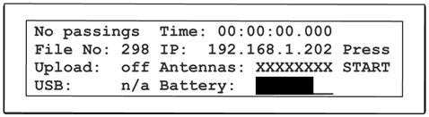

The display shows the following status information:
| Left Column | |
|
Count |
shows the number of detections since the last start, or No Passings. |
|
File No |
shows the number of the current passings file, see Test Mode and Timing Mode |
|
Upload |
shows the status of the server upload, see 2G/3G Upload |
|
USB |
shows the status of the USB stick, see USB Port |
| Middle Column | |
|
Time |
shows the running time (can be time of day or race time, see Time Setup) |
|
IP |
shows the IP address of the system, see Ethernet Connection |
|
Antennas |
shows the status of the eight passive antennas, or details of the Active Extension |
|
Battery |
shows the state of the internal battery, see Battery |
|
Right Column |
shows the ID of the last 4 transponders detected (or Press START when still in Test Mode, see Test Mode and Timing Mode) |
Battery
The decoder has an internal lead acid battery of 15Ah capacity which will last about 6-8 hours with the passive antenna or 24 hours with the active loop.
It can be charged while running, so it is recommended to connect the decoder to external power during the race when available.
Charging an empty battery takes approx. 4 hours when the decoder is turned off, and 8 hours when running. The LED Battery Charged on the keypad indicates the battery has been charged by at least 75%.
The battery fulfills IATA Special Provisions A48 and A67. The system can hence be handled as common cargo for both air shipment and boat shipment.
Data Connections
The timing data (“detections” or “passings”) can be retrieved in four different ways:
- via the Ethernet interface
- via the USB port
- When uploading the data through the internal 2G/3G/4G module, the data can be downloaded from the Internet.
- By accessing the decoder through your browser
Ethernet/Network Connection
The Ethernet connection is the recommended connection type to read out live data from the system during the race. The system can be connected directly to a computer using a standard patch cable or cross-over cable, or be integrated in a local network using a switch or router.
The RACE RESULT System offers two Ethernet ports and both ports can be used to connect to a computer/switch. The additional port can be used, for example, to connect to another RACE RESULT System (pass through). Both Ethernet ports and the RACE RESULT System itself are connected via an internal switch.
The parameters of the Ethernet connection can be defined in the Network menu.
By default, it is set to DHCP so that the system retrieves a dynamic IP address from a router/DHCP server in your network. For race timing it may be better to assign fixed IP addresses to each system. For that, simply turn off DHCP and enter the IP address manually (you can also set the subnet mask, standard gateway and DNS server which will be necessary when the decoder needs to access the Internet, e.g. for a firmware update).
For more information on network configuration see our Networking Guide
USB Port
The USB port serves to save the detection files on a USB stick. This can be done either after the race or live during the race. When plugging in a USB stick, the decoder will show a message that a stick has been detected and will copy all existing passing files to the stick. A separate folder named by the decoder ID will be created on it.
If a USB stick is plugged in during the race, the system will save the new detections every few seconds on the stick. This can serve as an additional backup: theoretically, even if the decoder had burnt down, the passing data is still stored on the USB stick which can be pulled out.
 Please do not remove the stick while the system is in Timing Mode. This may destroy the file system on the stick.
For the data format of the passing files, please refer to Data File Format.
Mobile Upload
The integrated 4G module (previously 2G or 3G) can be used to upload the detection data to a RACE RESULT database in the Internet. The data can then be downloaded from any place with an Internet connection. In other words, this is an easy way to connect remote timing points.
Upload
To upload the detections using the 4G/LTE module proceed as follows:
- Insert your SIM card in the SIM card slot.
- Go to the menu Upload.
- Enter your RACE RESULT customer number and the PIN of your SIM card
- Leave the mobile APN config setting on "auto". Your provider settings will probably be automatically recognized by the decoder. If not, select "manual" and read the sub-section of this article below to find out how to set up your APN.
- Set the option Enabled to yes.
The modem will go through successive connection stages detailed below as well. Once upload is successfully activated, the upload count on the display should match the current detection count.
You can also upload the data via an Ethernet connection with Internet connectivity. If the the decoder has access to the Internet via one of its Ethernet ports, the IP information on the display is marked with an asterisk. The upload feature automatically uses Ethernet when available, and falls back to 4G if the connection via Ethernet is lost.
Mobile Usage
In the second page of the Upload settings you can set the preference for usage of mobile upload.
There are 3 options for mobile upload.
- Fallback - The mobile GSM will only connect if upload is enabled and no internet connection is available via either the ethernet or via USB Wi-Fi adapter. If the connection drops from a preferred source then the module will attempt connection.
- Hot-Standby - The mobile GSM will connect always even if an alternative internet connection is available. If the connection drops from a preferred source the system will immediately switch to this.
- Preferred - The mobile GSM upload will be used at all times regardless of internet connection via either ethernet or USB Wi-Fi adapter.
Upload Target
In the second page of the Upload settings you can also set the upload target for the data.
As of firmware version 2.58, there are 2 options for upload when working with RACE RESULT 12.
- race result - This uploads via TCP protocols for communication with the Timing Module. This also includes an HTTP fallback in the event that the TCP connection is unstable which will also provide data to the Timing Module.
- race result (obselete) - This uploads data to our HTTP server, this will be fully deprecated at the end of 2021 and should not be used.
Download
When using RACE RESULT 12, you can download the passing data in the Timing Module.
To download the data using your own software, please consult Online Storage Communication Protocol.
Browser Access
You can easily access the decoder by entering the IP address in your browser, e.g. http://192.168.1.43
In the browser you can:
- Access all (old) passing files. Note that you cannot delete passing files. When the internal memory of 85 MB is full (it can save over 1 million detections), the oldest files will be deleted automatically.
- Access emergency data files. These are created during test mode and are stored automatically when timing is stopped.
- Set the time zone
- Configure upload settings including Custom APN Configuration, upload target and client mode.
- Upload Diagnostics Data
- Check the status of connected Loop Boxes
- Start / Stop Timing mode
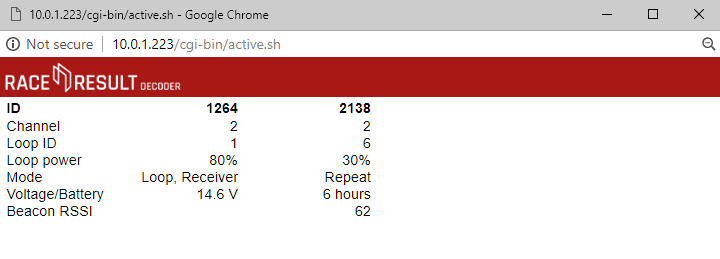
Show Active Systems
When connected to an active extension there is an option to view active systems, this allows you to see the status of the active extension and any connected loop boxes. This will open in a new mini window.
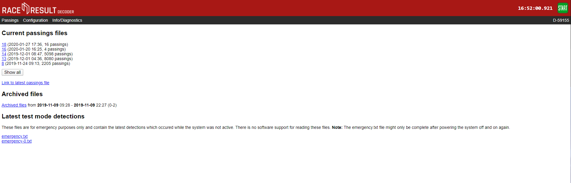
Passings
All passings files on the decoder can be accessed through the browser interface, any non-archived files will be shown immediately, when files are archived they are grouped together by the date range and can be downloaded.
There are 2 emergency files which are also available, these store the last detections from when the decoder was in test mode. emergency.txt is the most recent and emergency-0.txt is older passings.
There is no support to read this directly in to RACE RESULT 12 and so these files should not be relied on for timing.
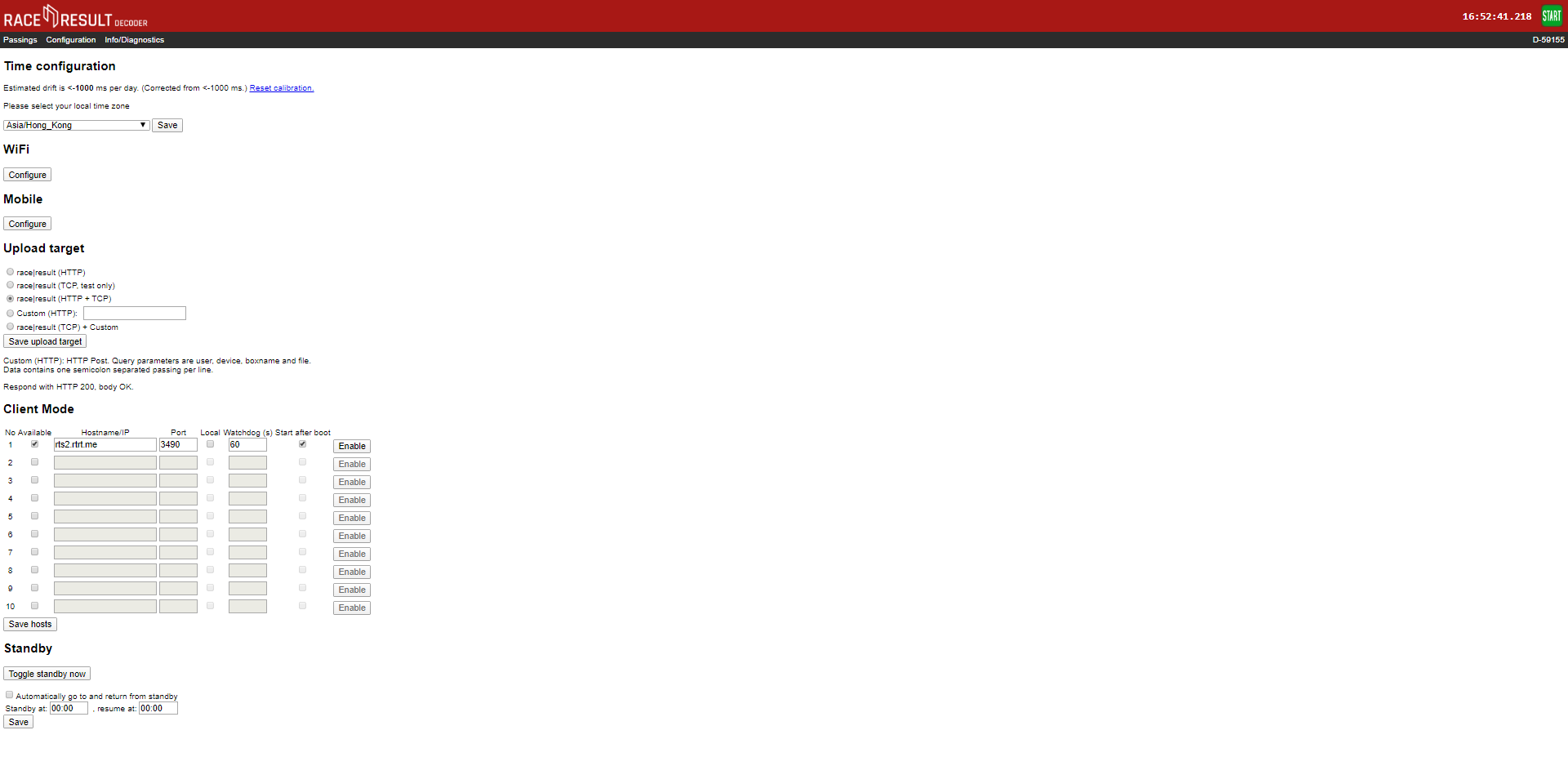
Configuration
The configuration tab allows for some additional configuration of settings which cannot be achieved through the decoder menu.
Time Drift
Here you can view the estimated time drift, this is the variation in time that may occur on the decoder, leaving the decoder turned on connected to the internet via ethernet can help to reduce this time drift, resetting the calibration will force the decoder to recalculate the time drift.
Time Zone
The time zone of the decoder can also be changed here using the drop down.
2G/3G
If you need to use custom APN settings for your Sim cards then these will need to be configured through the browser interface. You can also find your Decoders IMEI number from the Mobile Configuration page.
Upload Target
Decoders support upload to both HTTP and TCP, you can choose which method to use or define a custom HTTP target. HTTP upload is used for the Transponder module and Connector software, TCP upload is used for the new Timing Module. We advise using both HTTP and TCP for backup whilst the Timing Module is still undergoing development work.
Client Mode
You can use the decoder as a TCP server to pull data to a client, this is used by some third-party tracking platforms and timing software. There are a maximum of 10 TCP clients which can be configured with the IP address, port number, watchdog and auto-enable.
Find out more in our Developers Section
Standby
Standby is used in some permanent installations where the decoder can be powered down over night to preserve battery, it is not advised to set this for normal events as it could cause premature shut down.
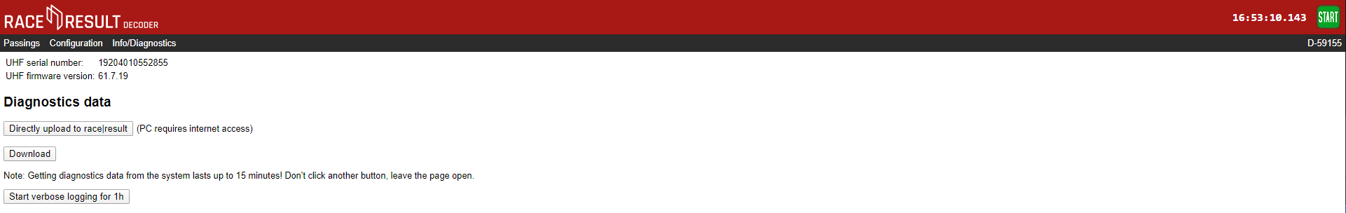
Info / Diagnostics
The info tab shows the UHF reader serial number and firmware version, and also allows you to upload the decoders diagnostics file directly to race result or download it to send to us. This may be required if you experience abnormal behaviour with your decoder during it's use.
Data File Format
The passings in the passing files are stored in the following format:
<PassingNo>;<Bib/TranspCode>;<Date>;<Time>;[<EventID>];<Hits>;<MaxRSSI>;
<InternalData>;<IsActive>;[<Channel>];[<LoopID>];[<LoopOnly>];[<WakeupCounter>];
[<Battery>];[<Temperature>];[<InternalActiveData>];<BoxName>;<FileNumber>;[<MaxRSSIAntenna>];<BoxId><CrLf>
|
<PassingNo> |
Passings record number, starting at 1 for the first passing. |
||||||||||||||||
|
<Bib/TranspCode> |
Bib number of the transponder (or transponder code in case of multi use tags or Active transponders) |
||||||||||||||||
|
<Date> |
Format: yyyy-MM-dd |
||||||||||||||||
|
<Time> |
Time of the detection, format: hh:mm:ss.kkk |
||||||||||||||||
|
<EventID> |
ID of the bib set. The combination of <Bib> and <EventID> is unique for all RACE RESULT Bib Transponders ever produced. |
||||||||||||||||
|
<Hits> |
Number of times the tag was detected. |
||||||||||||||||
|
<MaxRSSI> |
Maximum RSSI value found while determining <Time>. |
||||||||||||||||
|
[<InternalData>] |
This field is only used for internal purposes and is optional. |
||||||||||||||||
|
<IsActive> |
1 if this passing is from an active transponder |
||||||||||||||||
|
[<Channel>] |
Channel ID (1 -> 8) |
||||||||||||||||
|
[<LoopID>] |
Loop ID (1 -> 8) |
||||||||||||||||
|
[<LoopOnly>] |
1, if this detection was generated in Store Mode. |
||||||||||||||||
|
[<WakeupCounter>] |
Overall wakeup counter of the transponder (new transponders start at 10000). |
||||||||||||||||
|
[<Battery>] |
Battery level in Volts. |
||||||||||||||||
|
[<Temperature>] |
Temperature in degrees Celsius. |
||||||||||||||||
|
[<InternalActiveData>] |
Data transmission details. One byte. Lowest three bits: channel busy counter (number of times, the passing could not be transmitted because the transponder could not access the channel). Next three bits: no ACK counter (number of times the passing was transmitted, but no acknowledgement was received.) Seventh bit: 1, if this passing could not be transmitted at all in a previous attempt (="stored passing", old passing), 0 otherwise. Highest bit: 1, if the transponder woke up from deep sleep because of the passing, 0 otherwise. Hint: You can check if a passing is a stored passing using[InternalData] & 0x40 == 0x40 (the seventh bit is set)
|
||||||||||||||||
|
<BoxName> |
Name of the decoder. Defaults to the Device ID. |
||||||||||||||||
|
<FileNumber> |
File number of the file to which this passing belongs. | ||||||||||||||||
| [<MaxRSSIAntenna>] | Antenna number (1..8) which meassured the highest RSSI value. Empty for active. | ||||||||||||||||
| <BoxId> | Device ID | ||||||||||||||||
Client Mode
Client mode is used for outgoing connections to third party software / platforms, it is configured through the decoder Browser Access, client mode can be used to connect to either local TCP/IP servers or online servers. Common uses include third-party tracking platforms and photofinish software integration.
When client mode is enabled the decoder will try to make a connection to the specified server, once connected it allows for the server to send commands to the decoder to pull data and also change settings.
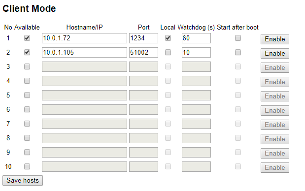
To configure Client Mode you will need the server hostname / URL / IP address and port number, if the server is on the local network then ensure to tick local. The watchdog is the frequency at which the decoder expects commands from the server otherwise it will try to reconnect.
When Client Mode is enabled the upload counters on the screen will cycle between your normal upload counts (Upload / HTTP Up) and TCP Out. TCP Out will show the number of connections which are active through Client mode, if it shows 1 or more then it is connected to the server(s).
Test Mode and Timing Mode
After booting, the decoder is in Test Mode, i.e. it does not store any detections. Instead, it steadily beeps/blinks when seeing a transponder. This way:
- The setup of the system can be checked easily to make sure it detects as expected.
- You do not need to filter any detections in the scoring software from athletes' warm-up before the race.
Timing Mode
The Timing Mode will be started when pressing the START button on the key pad. If not running on day time/GPS time, the time will start from 0:00:00 and the decoder will immediately start processing and recording every tag passing the antenna.
Stopping Timing Mode
The Timing Mode can be stopped by pressing the Cancel button or by selecting the entry Stop Timing in the menu. The system will then be back in Test Mode.
Next time the Timing Mode is started, the system creates a new file for the detections, indicated by a new file number on the main screen. Note that:
- Through the Ethernet interface, only detections from the current file can be read.
- All (old) files can be accessed any time through the browser or USB stick (see Data Connections).
Emergency File
If you forget to start Timing Mode, you can still access an emergency passings file through the Browser Access.
Time Setup
While in Test Mode the time of the decoder can be set via the Time menu. The following options are available:
Set Running Time
The time entered will be set and start running even while being in Test Mode. This option is usually used to set the clock time / time of day.
Set Start Time
The time entered will be set, but will not start running before starting the Timing Mode. This option is usually used to set the time to 0:00:00.
Set GPS Time
When using this option the system will try to receive the precise time from a GPS satellite. It may be that the GPS signal cannot be received inside buildings and under trees. In this case the system will show an error message after 60 seconds.
Configure GPS Time
Within the configuration you can set the time zone the decoder should use and adjust the value for Leap Seconds (this is normally only required when working with third-party hardware which does not correct for Leap Seconds).
Detection Setup
Reaction Time
As a chip approaches the ground antenna, the RACE RESULT System monitors the signal strength of the chip. After it passes over the antenna, the system records the time of the highest signal strength, which is expected to be directly above the antenna. The Reaction Time in the Detection menu defines for how much longer a chip will be monitored after the last signal strength peak before providing the final time.
When increasing the reaction time, the calculated finish times will be more precise but it takes longer until the system can provide this time. When using a small reaction time, the system can return the detection very quickly, but the precision will be reduced.
The default value is 850ms. If necessary, this value can be decreased for fast races (e.g. mountain bike) and increased for slow races (e.g. children). For optimum precision, the reaction time value should match the average time the chip will be in range of the antennas.
Note that the reaction time setting in the decoder only applies to the passive system. For the active system, the calculation of the time happens at transponder level.
Dead Time
The Dead Time in the Detection menu defines the minimum time between two reads of the same chip.
In the passive legacy mode Detection every dt ms and when using the active system, the decoder simply ignores further reads of the same chip for the duration of the dead time, after a first read has been stored.
In the First detection only, Last detection only, First + last detection modes that were introduced in more recent versions of the firmware, the decoder checks if the chip is still in range for the duration of the dead time after a first read has been stored.
The default value of the dead time is 5000ms. It can be set to value between 0 and 9999ms.
Detection Mode
The RACE RESULT System supports four different passive detection modes:
- First+last detection (default): the decoder stores a first detection based on the value of the reaction time. If the chip stays in the field after this first detection, the decoder will wait for the chip to leave the field for a duration higher than the dead time, and additionally report the last detection before the chip exited the field.
- First detection only: the decoder stores a first detection based on the value of the reaction time. It only stores a new detection for the same chip after the chip has been out of the detection field for a duration higher than the dead time.
- Last detection only: when the chip enters the detection field, the decoder looks for it for the duration of the dead time. When it does not see the chip for a duration higher than the dead time, it stores the last detection before the chip exited the detection field.
- Detection every dt ms: the decoder stores a first read based on the value of the reaction time, then it simply ignores any further reads of the same chip for the duration of the dead time.
First+last detection mode is the default, as it is the one that gives you the most complete information in any situation (a start, a split, or a finish) and lets you pick the right read at software level. First detection only and Last detection only are designed for special cases and should be used with extreme care, e.g. only use the former for a finish or a split timing location, and the latter in a start scenario.
Initially, only the legacy mode Detection every dt ms was available. We recommend not to use it anymore, especially in a start scenario. If a participant stands on the line for a long time before the start, you will typically receive a lot of detections (one every 5 seconds), where you only need the last one. Using this mode, the last detection is unprecise, and if the runner is detected right before the gun fires and leaves the detection field before the dead time is elapsed, you will not have a valid start detection after T0. The new modes came about precisely to address these issues.
Beep / Blink
The On Detection setting in the Detection menu defines whether the decoder should beep and / or blink to signal a detection.
Note that there is limit to the frequency of the beeps and blinks, these are only queued for 2 seconds. If too many athletes are being detected at the same time, the system will not be able to beep and blink for every athlete, and you would not be able to make out every separate signal anyway.
If the density of athletes crossing the timing system is low, the system will signal every detectoin separately with a short delay so that you can verify the number of detections easily.
Active Extension Settings
| C | h | a | n | n | e | l | : | 7 | |||||||||||||||||||||||||||||||
| P | o | w | e | r | : | 0 | 4 | 0 | % | | | . | . | . | . | . | . | . | . | . | . | . | . | . | . | . | . | . | . | . | . | . | . | | | ||||||
| L | o | o | p | I | D | : | 1 | ( | B | a | s | e | ) | ||||||||||||||||||||||||||
| D | i | s | c | a | r | d | s | t | o | r | e | d | d | e | t | e | c | t | i | o | n | s | : | N | O |
Channel
For the Active Extension, by default the Channel ID is set to auto. In this case, the system performs a channel survey when turned on and selects the channel used the least in order to avoid interferences between the active system and other devices. Note that
- Even if a channel is heavily used by Wi-Fi, there would still be sufficient gaps to operate the active system on the same channel.
- Auto mode will usually select channel 1 because this channel is not used by Wi-Fi and is often completely free.
If necessary, a different channel can be selected, when selecting the channel setting the system will first perform a channel survey and then show the channels and their qualities. You should select the channel(s) with the highest percentage, this is the clearest channel and will have the least interference.
| C | h | a | n | n | e | l | s | ( | Q | u | a | l | i | t | y | ) | |||||||||||||||||||||||
| A | l | w | a | y | s | s | e | l | e | c | t | c | h | a | n | n | e | l | a | u | t | o | m | a | t | i | c | a | l | l | y | ||||||||
| 1 | ( | 3 | 2 | % | ) | 2 | ( | 3 | 6 | % | ) | 3 | ( | 0 | % | ) | 4 | ( | 0 | % | ) | ||||||||||||||||||
| 5 | ( | 5 | 0 | % | ) | 6 | ( | 1 | 0 | % | ) | 7 | ( | 6 | 5 | % | ) | 8 | ( | 6 | 1 | % | ) |
Power
Adjust Loop Power using the left and right arrow keys, to understand how Loop Power impacts performance see Loop Power.
Note that the Active Extension automatically determines the length of the loop and adapts the real power on the loop accordingly, so that the same percentage value should always result in roughly the same read height.
Loop ID
Similar to the channel, the Loop ID normally runs in an auto mode. The RACE RESULT Active Extension, USB Timing Box, and Loop Box, each send out a status beacon every second on their Repeat channel. When turning on an Active Extension with auto loop mode, it will listen a few seconds for the signals from the other Active devices and then select an unused Loop ID.
The auto loop mode is easy to use, but it may be easier to assign fixed Loop IDs so that you immediately know which Loop ID belongs to which device. Make sure not to assign a Loop ID twice - otherwise you will receive the detections on both Active devices (when running on the same channel).
If you accidently select a Loop ID which is already being used, the Loop ID will flash between the occupied Loop ID and an X. The example below shows a RACE RESULT System with a Loop ID which has already been selected. Another Active device has been assigned this Loop ID, so it should not be used.
| C | o | u | n | t | : | 3 | 8 | 2 | 3 | T | i | m | e | : | 1 | 1 | : | 4 | 0 | : | 2 | 3 | . | 3 | 2 | 3 | z | z | z | z | z | 0 | 1 | ||||||
| F | i | l | e | N | o | : | 2 | 9 | 8 | I | P | : | 1 | 9 | 2 | . | 1 | 6 | 8 | . | 1 | . | 2 | 0 | 2 | z | z | z | z | z | 0 | 1 | |||||||
| U | p | l | o | a | d | : | o | f | f | C | h | # | : | 1 | L | o | o | p | # | : | X | 5 | 0 | % | z | z | z | z | z | 0 | 1 | ||||||||
| U | S | B | : | n | / | a | B | a | t | t | e | r | y | : | █ | █ | █ | █ | █ | █ | █ | █ | z | z | z | z | z | 0 | 1 |
V1 Legacy Mode
By default the V1 Legacy Mode is set to AUTO, in this mode it will use both the primary and backup channels to receive passing data, however if a transponder is detected which does not support this then the switching will be disabled until the system is rebooted or the setting is modified manually.
Channel switching can be set to ON to always keep it on, or OFF to always disable it, however this is not recommended since forgetting to change the setting back could have a negative impact on the data transmission.
Active Transponder Processing
The Active Transponder Processing determines how quickly Active passings will be processed and stored, there are three available modes.
- Smart
The system compares the Channel and Loop IDs of the passing to the current settings of the Active Extension. If the system receives passings with different IDs (e.g. from a Loop Box) it will enter a delayed mode. The system will then wait for 500ms to sort the passings to try and ensure they are stored in the correct order. The delayed mode is disabled again if no transponder is seen with a different Channel and Loop ID.
- As fast as possible
This is especially designed for TV productions. The system will store and forward the passings immediately. If the timing point has a lot of traffic over the 2.4GHz then it is possible that the passings are stored in the wrong order.
- Wait at least
Define a custom timeout for how long the Decoder should wait to sort the passings before storing them.
Feature Port
The feature port serves to connect any type of accessories to the RACE RESULT System. It provides ground, +12V, +5V, RX and TX. Besides the Active Extension (see Active Loop Setup) there are several Accessories you can connect.
The pins on the feature port are used as follows:

1: +4,8V output (5V - Shottky diode) (500mA max)
2: +11V-15V (unfused! two way!)
3: TXD 3,3V TTL
4: RXD 3,3V TTL internal Pull Up 10k
5: IO Digital Trigger - max 3,3V
SHIELD = GND
 Connect non RACE RESULT equipment at your own risk!
Short circuits will damage the system.
Only use original Neutrik connectors, cheap connectors do not connect GND reliably.
External Battery Port
The internal battery of the RACE RESULT System lasts for approximately 6-8 hours (passive ground antenna), or 24 hours (active loop). The external battery port can be used to connect a larger battery or a car (via the cigarette lighter) for longer uptimes without another power supply.
When determining the necessary size of a battery, calculate with a power consumption of 2 A using the passive antenna and 500mA using the active loop.
The system is sold with a special cable with XLR connector for the decoder on one end and a car connector on the other end. The pins are used as follows:

1: GND
2: +12V Input (10A Fuse)
3: NC
SHIELD = GND
Note that the external battery does not charge the internal battery, but instead power will be taken from both batteries, internal and external, at the same time.
You can use the Battery Booster to discharge the external battery first.
Startup Options
In the System menu the Startup option can be set to the following values:
| do nothing | Do nothing after normal startup. |
| set GPS time | Set GPS time after decoder has booted. |
| GPS time & activate | Set GPS time and activate operation mode after decoder has booted. |
| GPS time, activate & upload | Set GPS time, activate operation mode and upload (with current settings) after decoder has booted. |
| GPS time & upload | Set GPS time and start upload (with current settings) after decoder has booted. |
Trigger Impulse / Marker
When pressing the START button again in Timing Mode, an additional marker will be created. A marker is a fake detection with a certain bib number which can be used in the scoring software, e.g. to indicate the start of a second start wave.
To enable markers open the Trigger Impulse settings from the Menu, the Timing mode should be set to "default (+marker)".
Warning: Changing this without understanding the other modes will result in lost timing data. See Alternative Timing Modes.
Changing the Marker will cycle between 'off', the marker number which can be edited and the option to create a new file instead of a marker. It is good practice to ensure that the marker number does not overlap with your bib number ranges, this can be set to any value up to 999999. There also is an option to increase this number every time a marker has been created.
Markers can be set using accessories for the Feature Port or 3.5mm input of the Active Extension or Loop Boxes. To use the active extension input then ensure to change the I/O setting, on the second page of the Active Extension menu, to "Trigger In".
If using external inputs such as photocells or start gates you may wish to set the External Start setting to "yes". With this enabled the sensitivity of the trigger is increased to ensure all triggers are captured. When set to no the trigger pin is rechecked after a short delay (50ms) to prevent false triggers, but with high speed events this could result in missed triggers.
In RACE RESULT 12 markers are automatically identified and listed in the Start Times / Finish Time Limits menu, markers are stored internally with a bib according to the marker number set on the decoder.
Caution: If a marker number matches the bib of a participant in the event file then the marker will be assigned to the participant.
Alternative Timing Modes
Warning: These settings should be used with great caution, they are no longer recommended when timing/scoring with RACE RESULT 12 as markers can be assigned directly in the software.
By default the Timing Mode is set to +Marker which will add markers in to the passing file with the assigned marker number.
Alternatively it is possible to match markers to transponder reads on the decoder directly, this is used at events such as MTB downhill where the transponder is used for identification but the time should be taken from a marker from a trigger input such as photocells.
Depending on the setup you can assign the system to look for either: Chip first (1. Chip, 2. Photo cell) or the marker first (1. Photo Cell, 2. Chip).
A maximum time between chip / cell can also be set.
If a marker is not received in accordance to the rules, then the transponder time is not saved. For this reason this mode must not be used under normal circumstances.
Online Firmware Update
There are frequent firmware updates, e.g. for new features or new accessories. It is recommended to update the firmware frequently. See Firmware Release Notes.
Proceed as follows to update the firmware of your decoder:
- Make sure, the system is connected to external power, so that it does not run out of battery during the update process.
- Connect the decoder to the internet via ethernet cable, we recommend connecting directly to your internet router.
- Make sure DHCP is used or make sure the standard gateway and DNS server are set correctly (see Ethernet Connection).
- Go to the main menu, select the entry System, select Check online for new firmware and press the OK button. The system will now do the update process and then restart.
A standard firmware update requires around 15 MB of data, or up to 25 MB if it also contains an update of the UHF reader's firmware.
Recommendation: we don't suggest running the decoder's FW update over mobile connection, as it may not always be successful.
Decoder Configuration File
You can export a configuration file from one decoder, modify it and upload it to another decoder. This makes it much easier to configure all of your decoders the same way. This also gives you the ability to configure a decoder from your computer with a text file.
Downloading the Configuration File
As of firmware version 2.55 the decoder configuration file is copied automatically when a USB drive is plugged in to the decoder, the same way in which passings files are also copied. The file by default will use the decoder ID and is saved as a .toml file which is a standard type for configuration files.
On the System Menu there is an option to determine whether the exported configuration file will contain passwords or not, this is set to no by default. If enabled then passwords will be stored as plain text in the file.
Modifying the Config File
You can edit a decoder configuration file in any text application.
When changing a setting only apply values that are available within the decoder. For example, the On Detection setting has only three modes; BEEP, BLINK or BEEP and BLINK. You can not create a new mode where both BEEP and BLINK are false.
The available options for the configuration file are outlined below.
To avoid overwriting the original configuration file, always make sure to save your custom file with a new file name and set a new title. Files will be displayed on your decoder by their title name within the configuration file, not their filename.
Applying a new Config File
To upload a decoder configuration file you need to place the file on a flash drive within the raceresult folder, it is easiest to use a USB drive which already contains the automatically copied file directory.
e.g. raceresult>D-5662>MyCustomConfig.toml
Once you have added your configuration files to your USB drive, plug the USB drive into your decoder. You will be asked if you want to view the available configuration files.
| C | o | n | f | i | g | u | r | a | t | i | o | n | f | i | l | e | s | f | o | u | n | d | . | S | h | o | w | l | i | s | t | ? | |||||||
| D | o | n | o | t | u | n | p | l | u | g | d | r | i | v | e | w | h | i | l | e | f | l | a | s | h | i | n | g | ! | ||||||||||
| > | n | o | < | ||||||||||||||||||||||||||||||||||||
| y | e | s |
If you do not want to upload a new configuration you can press no, otherwise select yes to view the available files.
| C | h | o | o | s | e | a | c | o | n | f | i | g | f | i | l | e | . | ||||||||||||||||||||||
| P | r | e | s | s | C | a | n | c | e | l | t | o | a | b | o | r | t | . | |||||||||||||||||||||
| D | - | 5 | 6 | 6 | 2 | S | a | m | p | l | e | 1 | |||||||||||||||||||||||||||
| > | O | K | < |
If more than one configuration file is present on the USB drive then you can scroll left/right to select the file you want to upload and then press OK. All of the settings in the file will be used to update your decoder settings.
Passive Detection Data
With each read the system saves some useful information about the passing, understanding this can help to better interpret your data and identify potential problems.
As well as the basic information including the Time and Decoder ID, the following data is recorded for a passive read:
- OrderID - The ID number of the order for which the transponder was printed.
- Hits - The number of times the chip was seen by the decoder during the passing (Not applicable to Track Box Passive data, you should expect lower hits due to the transponder communication protocols).
- RSSI - The strength of the signal received (in dBm) from the passing when the read was recorded.
- A higher value is a stronger detection. For example -42 is better than -60. The best possible value is -35 and the worst value is -85dBm, this is the sensitivity limit.
- Typical values are in the range of -50dBm..-70dBm.
- The RSSI value is the value of the best hit according to your decoder's detection mode.
| Guidelines for detection strength | Hits | RSSI |
| Perfect (could not be better) | 75...255 | -35...-55 |
| OK (nothing to worry about) | 20...75 | -55...-65 |
| Not Great (still working, but could be better) | 5...20 | -65...-75 |
| Barely Detected (setup should be checked) | 1...10 | -70...-85 |
| Transponder is in range but not moving* | high value | low value |
*Such as a participant who has already finished watching the race near the finish line whilst still wearing their transponder.
Technical Specification
Safety & Conformity |
|
|---|---|
|
Protection Class (Lid Closed) |
IP54 -water resistant- |
| Regulatory Conformity and Standards | EN60950 (safety) CE, RoHS, FCC |
| Relative Humidity |
maximum 90% non-condensing |
| Temperature Range | -20°C to 50°C |
| Dimensions / Weight |
36cm x 26cm x 45cm 12.5kg |
Power & Battery |
|
|---|---|
|
AC Power Supply |
110V - 230V, 50/60Hz 2A fuse |
| DC Power Supply |
12V - 14V 2A (when battery full) |
| Battery Flight Safety |
15Ah (Pb) IATA - A48 / A67 |
| Charging Time |
4h (switched off) 7h (running) |
| Power Consumption |
26W (battery full) 60W (battery charging) |
| Battery Life (Passive) | 8h - 10h [1] |
| Batter Life (Active) | 24h [1] |
[1] Battery life can be reduced by usage of LTE/4G (-10 %), low temperature (-25 % @ 0°C/32°F) and battery age
Connectivity |
|
|---|---|
|
29 Band 4G / LTE / 3G / 2G Module (Worldwide Coverage) |
FDD: B1 / B2 / B3 / B4 / B5 / B7 / B8 / B12 / B13 / B18 / B19 / B20 / B26 / B28 TDD:B38 / B39 / B40/ B41 WCDMA: B1 / B2 / B4/ B5 / B8 / B6 / B19 GSM: B2 / B3 / B5 / B8 |
| Antenna |
Internal External SMA (optional) |
| SIM Card |
2FF standard |
| Charging Time |
4h (switched off) 7h (running) |
Ports & Features |
|
|---|---|
|
Internal GPS |
uBlox 50 channel receiver, 30 seconds cold start |
| 2 x LAN |
dual 100MB / 10MB LAN port auto crossover detection switched internally for loop through to next device |
| USB |
storage drive for backup Wi-Fi adapter (optional) |
| Antenna Ports |
8 x BNC |
| Feature Port |
supplies 5v (500mA), 12v (500mA) output, start gun / photo sensor input |
| Audio Beep | 3.5mm headphone plug (mono) |
RACE RESULT Decoder FAQs
New Decoder Setup
When receiving a new RACE RESULT decoder you will want to take some steps to configure it to your required settings. Below are some of the key settings to consider when setting up a new decoder.
Time Zone
The decoder is able to sync to GPS time using the onboard module which is the recommended method for syncing time during a race. You will need to set the time zone to your local time zone to ensure the GPS time is correct.
To do this the decoder must be in Test mode, open the Menu and navigate to Time -> Configure GPS Time
The default Time Zone will be Europe / Amsterdam, to change this highlight the time zone, press OK and use the left/right arrows to change the time zone.
IP Address
By default the decoder will use DHCP to receive an IP address automatically from the network. If using a network with fixed IP ranges or connecting directly from your decoder to a laptop with no network then you may need to set a static IP address.
The IP address can be configured in the network menu, you will need an understanding of Managing IP Configuration.
Upload
If using the upload from the decoder to access the system online you will need to ensure the upload is correctly configured for your account.
Open the menu and navigate to Upload, in here you will need to set the Customer ID to your RACE RESULT customer ID which you will use to login to RACE RESULT 12. The decoder will only be available to this account.
If using the internal GSM module with SIM card then you may need to check the APN settings, by default the decoder will use AUTO APN settings, which work for most major providers worldwide, however some may require custom settings, in particular if using a SIM PIN.
APN settings can only be configured through the decoder browser interface which can be accessed in your web browser by entering the IP address of the decoder when connected via a local network.
Startup Options
To save time and simplify setup, particularly for remote splits, it is possible to set the decoder to automaticallys set / enable key settings during the startup. You can set all, none or any combination of the following settings:
- Set GPS Time
- Activate Timing Mode
- Enable Upload
To enable the startup options open the Menu and navigate to System, highlight the startup options and press OK to cycle through the options.
Marker
If using the decoder to set a marker (time stamp) then you will need to enable the marker, since this is not enabled by default.
To enable markers open the menu and navigate to Trigger Impulse, highlight Marker (off) and press OK to cycle the menu to enable a marker number. The default marker will use number 99999, press OK again to change this number.
Configure GPS time on a 5000 series decoder
This article will teach you how to configure the Time Zone setting on your decoder and then sync your decoder to GPS time.
- NOTE: The MENU button is in the center. The OK button is on the lower right.
- Navigate to Menu > Time > Configure GPS time.
- Use the left and right arrow keys to select your correct time zone. Press OK to confirm.
- Press Cancel once to navigate back to the previous menu (Time menu).
- Select Set GPS Time and click OK. The decoder will then start searching for GPS satellites
- Wait for the decoder to connect to GPS.
- Once the decoder finds GPS, you will see a clock at the top of the screen. Make sure this is showing the correct time of day. If not, double-check your Time Zone and sync GPS time again.
The Time Zone setting is saved on your decoder. It will not need to be set again unless you change it or move to a different time zone.
You will need to sync GPS time each time the decoder turns on. If you want to automate this, you need to change the Startup Options under the System menu.
Decoder LCD Menus
This article documents all of the Decoder LCD screens for quick reference to each of the subsequent Knowledge Base articles for each section.
Passive Home Menu
| N | o | P | a | s | s | i | n | g | s | T | i | m | e | : | 0 | 0 | : | 0 | 0 | : | 0 | 0 | . | 0 | 0 | 0 | |||||||||||||
| F | i | l | e | N | o | : | 1 | 0 | I | P | : | 1 | 9 | 2 | . | 1 | 6 | 8 | . | 1 | . | 2 | 0 | 0 | P | r | e | s | s | ||||||||||
| U | p | l | o | a | d | : | o | f | f | A | n | t | e | n | n | a | s | : | █ | █ | █ | █ | █ | █ | █ | █ | S | T | A | R | T | ||||||||
| U | S | B | : | n | / | a | B | a | t | t | e | r | y | : | █ | █ | █ | █ | █ | █ | █ | █ |
Passive Main Menu
Click on a menu option to learn more.
| ➞ | T | i | m | e | ⬅ | U | H | F | S | e | t | t | i | n | g | s | |||||||||||||||||||||||
| D | e | t | e | c | t | i | o | n | T | r | i | g | g | e | r | i | m | p | u | l | s | e | |||||||||||||||||
| N | e | t | w | o | r | k | S | y | s | t | e | m | |||||||||||||||||||||||||||
| U | p | l | o | a | d | I | n | f | o |
Active Home Menu
| N | o | P | a | s | s | i | n | g | s | T | i | m | e | : | 0 | 0 | : | 0 | 0 | : | 0 | 0 | . | 0 | 0 | 0 | |||||||||||||
| F | i | l | e | N | o | : | 1 | 0 | I | P | : | 1 | 9 | 2 | . | 1 | 6 | 8 | . | 1 | . | 2 | 0 | 0 | P | r | e | s | s | ||||||||||
| U | p | l | o | a | d | : | o | f | f | L | o | o | p | # | : | 1 | C | h | # | : | 1 | 1 | 0 | 0 | % | S | T | A | R | T | |||||||||
| U | S | B | : | n | / | a | B | a | t | t | e | r | y | : | █ | █ | █ | █ | █ | █ | █ | █ |
Active Main Menu
Click on a menu option to learn more.
| ➞ | T | i | m | e | ⬅ | A | c | t | i | v | e | E | x | t | e | n | s | i | o | n | |||||||||||||||||||
| D | e | t | e | c | t | i | o | n | T | r | i | g | g | e | r | i | m | p | u | l | s | e | |||||||||||||||||
| N | e | t | w | o | r | k | S | y | s | t | e | m | |||||||||||||||||||||||||||
| U | p | l | o | a | d | I | n | f | o |
Menu->Time
For more information on time settings Time Setup
| ➞ | S | e | t | r | u | n | n | i | n | g | t | i | m | e | : | 0 | 0 | : | 0 | 0 | : | 0 | 0 | ⬅ | |||||||||||||||
| S | e | t | s | t | a | r | t | t | i | m | e | : | 0 | 0 | : | 0 | 0 | : | 0 | 0 | |||||||||||||||||||
| S | e | t | G | P | S | t | i | m | e | ||||||||||||||||||||||||||||||
| C | o | n | f | i | g | u | r | e | G | P | S | t | i | m | e |
Menu->Time->Configure GPS time Menu
| ➞ | T | i | m | e | z | o | n | e | : | E | u | r | o | p | e | / | A | m | s | t | e | r | d | a | m | ⬅ | |||||||||||||
| L | e | a | p | s | e | c | o | n | d | s | : | 1 | 8 | ( | d | e | f | a | u | l | t | ) | |||||||||||||||||
Menu->Detection Menu
For more information on detection settings Detection Setup
| ➞ | D | e | a | d | T | i | m | e | ( | d | t | ) | : | 0 | 5 | 0 | 0 | 0 | m | s | ⬅ | ||||||||||||||||||
| R | e | a | c | t | i | o | n | T | i | m | e | : | 0 | 0 | 8 | 5 | 0 | m | s | ||||||||||||||||||||
| M | o | d | e | : | F | i | r | s | t | + | L | a | s | t | D | e | t | e | c | t | i | o | n | ( | d | e | f | a | u | l | t | ) | |||||||
| O | n | d | e | t | e | c | t | i | o | n | : | B | L | I | N | K | + | B | E | E | P |
| ↑ | T | e | s | t | M | o | d | e | : | R | e | a | c | t | t | o | a | l | l | t | r | a | n | s | p | o | n | d | e | r | s | ↑ | |||||||
Menu->Network Menu
For more information on network settings Ethernet/Network Connection
| ➞ | U | s | e | D | H | C | P | f | o | r | E | t | h | e | r | n | e | t | : | n | o | ⬅ | |||||||||||||||||
| M | a | n | u | a | l | E | t | h | e | r | n | e | t | I | P | c | o | n | f | i | g | u | r | a | t | i | o | n | |||||||||||
Menu->Network > Manual Ethernet IP configuration
| ➞ | I | P | A | d | d | r | e | s | s | : | 1 | 9 | 2 | . | 1 | 6 | 8 | . | 0 | 0 | 1 | . | 2 | 0 | 5 | ⬅ | |||||||||||||
| S | u | b | n | e | t | M | a | s | k | : | 2 | 5 | 5 | . | 2 | 5 | 5 | . | 2 | 5 | 5 | . | 0 | 0 | 0 | ||||||||||||||
| S | t | d | . | G | a | t | e | w | a | y | : | 1 | 9 | 2 | . | 1 | 6 | 8 | . | 0 | 0 | 1 | . | 0 | 0 | 1 | |||||||||||||
| D | N | S | S | e | r | v | e | r | : | 1 | 9 | 2 | . | 1 | 6 | 8 | . | 0 | 0 | 1 | . | 0 | 0 | 1 |
Menu->Upload Menu
For more information on upload Mobile Upload
| ➞ | C | u | s | t | N | o | : | 1 | 2 | 3 | 4 | 5 | ⬅ | ||||||||||||||||||||||||||
| S | I | M | P | I | N | : | _ | _ | _ | _ | 1 | 1 | 1 | 1 | |||||||||||||||||||||||||
| M | o | b | i | l | e | A | P | N | : | a | u | t | o | ||||||||||||||||||||||||||
| E | n | a | b | l | e | d | : | n | o |
| ↑ | P | r | e | f | e | r | r | e | d | a | n | t | e | n | n | a | : | i | n | t | e | r | n | a | l | ↑ | |||||||||||||
| M | o | b | i | l | e | u | s | a | g | e | : | F | a | l | l | b | a | c | k | ||||||||||||||||||||
| M | o | b | i | l | e | D | N | S | : | 0 | 0 | 8 | . | 0 | 0 | 8 | . | 0 | 0 | 8 | . | 0 | 0 | 8 | |||||||||||||||
| O | n | l | i | n | e | - | c | h | e | c | k | I | P | : | 0 | 0 | 8 | . | 0 | 0 | 8 | . | 0 | 0 | 8 | . | 0 | 0 | 8 |
| ↑ | T | a | r | g | e | t | : | r | a | c | e | r | e | s | u | l | t | ↑ | |||||||||||||||||||||
| S | y | n | c | F | i | l | e | s | : | C | u | r | r | e | n | t | |||||||||||||||||||||||
Menu->UHF Subsystem Menu
| U | H | F | S | . | N | o | . | : | 0 | 1 | 2 | 3 | 4 | 5 | 6 | 7 | 8 | 9 | 8 | 7 | 6 | ||||||||||||||||||
| F | r | e | q | u | e | n | c | y | : | 9 | 0 | 2 | . | 8 | - | 9 | 2 | 6 | . | 2 | M | H | z | ||||||||||||||||
| ➞ | P | o | w | e | r | : | M | A | X | ⬅ | |||||||||||||||||||||||||||||
| A | p | p | l | y | p | e | r | m | a | n | e | n | t | l | y |
Menu->Active Extension Menu
For more information on setting up an Active Extension Active Loop Setup
| ➞ | L | o | o | p | I | D | : | 1 | ( | B | a | s | e | ) | ⬅ | ||||||||||||||||||||||||
| C | h | a | n | n | e | l | : | A | U | T | O | ||||||||||||||||||||||||||||
| P | o | w | e | r | : | 1 | 0 | 0 | % | | | . | . | . | . | . | . | . | . | . | . | . | . | . | . | . | . | . | . | . | . | █ | | | |||||||
| D | i | s | c | a | r | d | s | t | o | r | e | d | d | e | t | e | c | t | i | o | n | s | : | n | o |
| ↑ | D | i | s | c | a | r | d | d | e | t | e | c | t | i | o | n | s | < | x | h | i | t | s | : | 1 | ↑ | |||||||||||||
| P | r | o | c | e | s | s | i | n | g | : | S | m | a | r | t | ||||||||||||||||||||||||
| B | e | e | p | o | n | r | e | p | e | a | t | e | d | p | a | s | s | i | n | g | s | : | y | e | s | ||||||||||||||
| I | / | O | i | s | : | T | r | i | g | g | e | r | I | N |
| ↑ | V | 1 | L | e | g | a | c | y | m | o | d | e | : | A | U | T | O | ( | A | U | T | O | ) | ↑ | |||||||||||||||
Menu->Trigger impulse Menu
For more information on markers Marker
| ➞ | T | i | m | i | n | g | m | o | d | e | : | d | e | f | a | u | l | t | ( | + | M | a | r | k | e | r | ) | ⬅ | |||||||||||
| M | a | r | k | e | r | N | o | . | : | 1 | 0 | 0 | 0 | 0 | 0 | ||||||||||||||||||||||||
| I | n | c | r | e | a | s | e | m | a | r | k | e | r | n | o | . | : | y | e | s | |||||||||||||||||||
| E | x | t | e | r | n | a | l | s | t | a | r | t | : | n | o |
Menu->System Menu
For more information on firmware changes Firmware Revisions and how to update firmware Online Firmware Update
For more information on startup options Startup Options
| ➞ | S | t | a | r | t | u | p | : | d | o | n | o | t | h | i | n | g | ⬅ | |||||||||||||||||||||
| A | r | c | h | i | v | e | p | a | s | s | i | n | g | s | f | i | l | e | s | ||||||||||||||||||||
| R | e | s | e | t | A | l | l | s | e | t | t | i | n | g | s | ||||||||||||||||||||||||
| C | h | e | c | k | o | n | l | i | n | e | f | o | r | n | e | w | f | i | r | m | w | a | r | e |
| ↑ | U | p | l | o | a | d | d | i | a | g | n | o | s | t | i | c | s | d | a | t | a | ↑ | |||||||||||||||||
| P | a | s | s | w | o | r | d | s | i | n | c | o | n | f | i | g | e | x | p | o | r | t | : | n | o | ||||||||||||||
| S | w | i | t | c | h | t | o | n | e | w | s | t | o | r | a | g | e | m | e | t | h | o | d | ||||||||||||||||
Menu->Info Menu
| D | e | v | i | c | e | - | I | D | : | D | - | 1 | 2 | 3 | 4 | ||||||||||||||||||||||||
| D | e | v | i | c | e | M | B | / | F | W | : | < | 1 | . | 3 | - | 0 | / | 2 | . | 4 | 8 | |||||||||||||||||
| T | e | m | a | p | r | a | t | u | r | e | : | 4 | 2 | . | 0 | 0 | ° | C | / | 4 | 6 | . | 0 | 0 | ° | C | |||||||||||||
|
|
O | K |
|
On the line that says "Device MB/FW", the first number displayed (1.3) is the version number of the mainboard in your device. The second part (-0) shows that you have an older processor unit known as the TX-28. A -1 shows a newer processor. The last part (2.48) shows the firmware version of your decoder.
Know Mainboard versions with LCD reference.
| LCD Screen Shows | Mainboard Version |
| <1.3 | Mainboard version less than 1.3 |
| 1.3-1.4 | Mainboard version of 1.3 or 1.4 |
| 1.5 | Mainboard version 1.5 |
Leap Seconds
The decoder default for leap seconds is 18 seconds when using GPS time.
GPS time was set to "zero" at 00:00:00 on 1980-06-01, subsequently GPS time is now ahead of UTC time by 18 seconds as there have been 18 leap seconds since this date.
When the leap seconds value is updated we will include this in future firmware revisions.
The only time it may be necessary to modify the value for leap seconds is when using third party hardware alongside your race result decoder, other hardware may not update leap seconds to the same value.
Is the RACE RESULT System certified by IAAF?
To our knowledge, the International Association of Athletics Federation (IAAF) does not deliver an official certification for transponder timing systems used on road races.
However, the IAAF Competition Rules for 2018-2019, available for download at https://www.iaaf.org/about-iaaf/documents/rules-regulations, define in Rule 165 §24 a number of criteria for transponder systems used on road races and other events not held completely in a stadium.
Below, you can download a letter from our Head of R&D stating the RACE RESULT System meets the IAAF criteria.
Downloading a Passing File from a RACE RESULT Decoder
How to download a passing file to a USB stick.
1. Plugin a USB stick into the USB port on the decoder. You will see a message on the LCD screen like this. This is just to let you know that the decoder is going to upload all passings files to the USB stick. It is important that you do not unplug the USB stick while it is uploading data. This could cause file corruption.
| U | S | B | s | t | i | c | k | d | e | t | e | c | t | e | d | . | |||||||||||||||||||||||
| C | o | p | y | i | n | g | o | l | d | f | i | l | e | s | , | s | t | o | r | i | n | g | n | e | w | p | a | s | s | i | n | g | s | . | |||||
| D | o | n | o | t | u | n | p | l | u | g | U | S | B | s | t | i | c | k | w | h | i | l | e | f | l | a | s | h | i | n | g | ! | |||||||
|
|
O | K |
|
2. Once the message has been accepted you will see a screen like this with the USB text flashing. Do not remove the USB stick during this portion of the process.
| N | o | P | a | s | s | i | n | g | s | T | i | m | e | : | 0 | 0 | : | 0 | 0 | : | 0 | 0 | . | 0 | 0 | 0 | |||||||||||||
| F | i | l | e | N | o | : | 1 | 0 | I | P | : | 1 | 9 | 2 | . | 1 | 6 | 8 | . | 1 | . | 2 | 0 | 0 | P | r | e | s | s | ||||||||||
| U | p | l | o | a | d | : | o | f | f | A | n | t | e | n | n | a | s | : | █ | █ | █ | █ | █ | █ | █ | █ | S | T | A | R | T | ||||||||
| U | S | B | : | 2 | 0 | % | B | a | t | t | e | r | y | : | █ | █ | █ | █ | █ | █ | █ | █ |
3. Once the decoder is done uploading all files to the USB stick you will see a message like this. You will see the word "done" next to USB. this indicates the process is done and it is safe to remove the USB stick.
| N | o | P | a | s | s | i | n | g | s | T | i | m | e | : | 0 | 0 | : | 0 | 0 | : | 0 | 0 | . | 0 | 0 | 0 | |||||||||||||
| F | i | l | e | N | o | : | 1 | 0 | I | P | : | 1 | 9 | 2 | . | 1 | 6 | 8 | . | 1 | . | 2 | 0 | 0 | P | r | e | s | s | ||||||||||
| U | p | l | o | a | d | : | o | f | f | A | n | t | e | n | n | a | s | : | █ | █ | █ | █ | █ | █ | █ | █ | S | T | A | R | T | ||||||||
| U | S | B | : | d | o | n | e | B | a | t | t | e | r | y | : | █ | █ | █ | █ | █ | █ | █ | █ |
Now that you have your passing file on a USB stick see this article on Read Passings File through Timing Module.
Decoder warning/error screens
In rare cases you receive an error message / warning after the boot up process. Please find a list of error screens below as well as a description of what has caused the decoder to fail. Once you confirmed the error message, you will see a permanent error code where you usually see the antenna indicator on the screen. We investigate every failure, so please upload diagnostics of the affected decoder as soon as possible. Inform us about the uploaded diagnostics and include the following information:
- Decoder-ID
- Date/Time when you experienced the error
- Have you seen the error before on the same decoder?
- What have you done after receiving the error message (especially when you don't see it for the first time)?
Error messages
Noise:
| U | H | F | s | u | b | s | y | s | t | e | m | p | r | o | b | l | e | m | : | n | o | i | s | e | . | ||||||||||||||
| E | x | p | e | c | t | r | e | d | u | c | e | d | d | e | t | e | c | t | i | o | n | r | a | t | e | ! | |||||||||||||
| P | l | e | a | s | e | n | o | t | i | f | y | r | a | c | e | r | e | s | u | l | t | . | |||||||||||||||||
| ► | O | K | ◄ |
This is a non-fatal error. It is often raised when the antennas are not completely unfolded, if much metal is around the antennas or if other devices use the same frequencies. Usually it is safe to re-use the decoder and check if the problem persists at the next race/setup.Permanent error code: RF ERROR: NOISY ENV
llrp:
| U | H | F | s | u | b | s | y | s | t | e | m | p | r | o | b | l | e | m | : | l | l | r | p | . | |||||||||||||||
| E | x | p | e | c | t | r | e | d | u | c | e | d | d | e | t | e | c | t | i | o | n | r | a | t | e | ! | |||||||||||||
| P | l | e | a | s | e | n | o | t | i | f | y | r | a | c | e | r | e | s | u | l | t | . | |||||||||||||||||
| ► | O | K | ◄ |
This error is caused by a software level UHF reader disconnection, it may be caused by a command timeout or when the UHF reader was intentionally restarted. This does not represent hardware failure. Please upload the diagnostics file of the affected decoder. Permanent error code: FATAL ERROR: R-RES
Exception:
| U | H | F | s | u | b | s | y | s | t | e | m | p | r | o | b | l | e | m | : | e | x | c | e | p | t | i | o | n | . | ||||||||||
| E | x | p | e | c | t | r | e | d | u | c | e | d | d | e | t | e | c | t | i | o | n | r | a | t | e | ! | |||||||||||||
| P | l | e | a | s | e | n | o | t | i | f | y | r | a | c | e | r | e | s | u | l | t | . | |||||||||||||||||
| ► | O | K | ◄ |
Permanent error code: FATAL ERROR: R-EX
This error is caused by an unspecified rare UHF reader exception. Please upload diagnostics of the affected decoder so we can further investigate the failure.
Overload:
| U | H | F | s | u | b | s | y | s | t | e | m | p | r | o | b | l | e | m | : | o | v | e | r | l | o | a | d | . | |||||||||||
| E | x | p | e | c | t | r | e | d | u | c | e | d | d | e | t | e | c | t | i | o | n | r | a | t | e | ! | |||||||||||||
| P | l | e | a | s | e | n | o | t | i | f | y | r | a | c | e | r | e | s | u | l | t | . | |||||||||||||||||
| ► | O | K | ◄ |
Permanent error code: FATAL ERROR: R-SW
This error is displayed when there is no specific LLRP program error/exception, but the UHF reader does not respond to some monitoring checks (like temperature). Possible causes: temporary or permanent connection issue on the control channel. Could be an aftereffect of some other error which causes re-connects to the UHF reader. Please upload diagnostics so we can get to the root cause.
Cable:
| U | H | F | s | u | b | s | y | s | t | e | m | p | r | o | b | l | e | m | : | c | a | b | l | e | . | ||||||||||||||
| E | x | p | e | c | t | r | e | d | u | c | e | d | d | e | t | e | c | t | i | o | n | r | a | t | e | ! | |||||||||||||
| P | l | e | a | s | e | n | o | t | i | f | y | r | a | c | e | r | e | s | u | l | t | . | |||||||||||||||||
| ► | O | K | ◄ |
Permanent error code: FATAL ERROR: R-PHY
The Ethernet connection to the UHF reader is down. Either because the UHF reader is off or there is a problem with the connection between UHF reader and mainboard.
Fatal:
| U | H | F | s | u | b | s | y | s | t | e | m | p | r | o | b | l | e | m | : | f | a | t | a | l | . | ||||||||||||||
| E | x | p | e | c | t | n | o | d | e | t | e | c | t | i | o | n | s | a | t | a | l | l | ! | ||||||||||||||||
| P | l | e | a | s | e | n | o | t | i | f | y | r | a | c | e | r | e | s | u | l | t | . | |||||||||||||||||
| ► | O | K | ◄ |
Permanent error code: FATAL ERROR: R-LOG
The UHF reader log files indicate a fatal error. It could be that it won't detect at all. Instantly check whether or not this is the case.
Unknown:
| U | H | F | s | u | b | s | y | s | t | e | m | p | r | o | b | l | e | m | : | u | n | k | n | o | w | n | . | ||||||||||||
| E | x | p | e | c | t | r | e | d | u | c | e | d | d | e | t | e | c | t | i | o | n | r | a | t | e | ! | |||||||||||||
| P | l | e | a | s | e | n | o | t | i | f | y | r | a | c | e | r | e | s | u | l | t | . | |||||||||||||||||
| ► | O | K | ◄ |
Permanent error code: FATAL ERROR: R-UKW
Please upload diagnostics of the affected decoder so we can further investigate.
Timeout (PHY):
| T | i | m | e | o | u | t | w | a | i | t | i | n | g | f | o | r | R | e | a | d | e | r | ( | P | H | Y | ) | ||||||||||||
| b | o | o | t | i | n | g | . | . | |||||||||||||||||||||||||||||||
| w | a | i | t | a | n | d | p | o | w | e | r | o | n | a | g | a | i | n | . | ||||||||||||||||||||
| T | o | b | o | o | t | w | / | o | U | H | F | i | n | s | e | r | t | A | c | t | i | v | e | E | x | t | e | n | s | i | o | n | . |
Permanent error code: FATAL ERROR: PHY
Please upload diagnostics of the affected decoder so we can further investigate.
Warnings
Info:
| A | C | T | I | V | E | e | x | t | e | n | s | i | o | n | p | l | u | g | g | e | d | i | n | . | |||||||||||||||
| T | o | a | l | l | o | w | t | h | i | s | b | o | x | t | o | b | o | o | t | w | i | t | h | a | n | ||||||||||||||
| e | x | t | . | a | l | r | e | a | d | y | c | o | n | n | e | c | t | e | d | , | c | o | n | t | a | c | t | u | s | . | |||||||||
| ► | O | K | ◄ |
This info screen is displayed when the decoder thinks, it cannot boot while an active connection is connected. If the decoder actually boots with an Active Extension connected, all is good. If not, and you want this to be changed, please create a RMA and send the decoder in,
Upload Diagnostics Data
In some cases it may be necessary to send diagnostics data from your system directly to RACE RESULT for further analysis, this is a log of everything which has happened to the decoder including critical internal information. If you do this and have not been asked to then please also e-mail to support@raceresult.com explaining any potential issues with details, we cannot look through the entire log file with no previous information.
Uploading the diagnostics can be done in 2 easy ways:
Directly from RACE RESULT System (PREFERRED)
You can now upload this directly from your system, this option is preferred since the logs are stored on our server for easy retrieval and decrypting.
First you need to ensure that your decoder has an active internet connection, we recommend doing this by connecting your system via ethernet to your internet router, you may need to enable DHCP in your network settings. It can also be done via the on board 2G/3G module with a Sim Card however beware that this may incur data charges depending on your network provider, although the file itself is very small.
Once connected open the MENU then navigate to SYSTEM, you will need to scroll down to a second screen where you will see Upload Diagnostics Data, press okay and the system will automatically send the file directly to our support team.
Through Browser Interface
Please only use this option If it is not possible to connect your decoder directly to the internet.
You can also upload diagnostics through a computer which has an internet connection, your decoder will need to be on the same network as when you are connecting to a local device.
Once connected type in the decoder IP address in to your internet browser address bar, such as "192.168.1.68"
In the top navigation bar is a link to Info/Diagnostics, click this and you will see 2 options - directly upload to RACE RESULT or download so you can e-mail to us separately.
Simply choose your preferred method and send us the data, do note that it can take up to 10 minutes to collect the data during which time you should not navigate away from this page and the analysis may take longer due to the additional decryption required when received in this format.
How to locate Decoder IMEI number
Using the Browser Access for your Decoder you can go to Configuration > Mobile Configure. Here you will see the IMEI number under Modem Information.