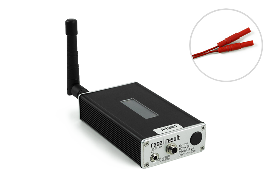
The Loop Box is an additional stand-alone device which activates the active transponder, but does not process the data of the transponders. Instead, the passing data will either be repeated to another box or be stored in the transponder.
In this section, the USB Timing Box and Active Extension will be referred to as the main loop.
Turning Loop Box on/off
To turn the box on, press and hold the button until the center red LED turns off and a boot screen is displayed with information about the system.
To turn off, press the button once. The screen will display the following:
| press again: OFF |
| hold for config |
Press the button again to turn off.
The box will also turn on automatically when connected to an external power supply and cannot be switched off.
When disconnecting from an external power supply the box will automatically shut down if there is no loop connected and no passings have been recorded on the device since it was started.
Loop Box Configuration
The Loop Box has the same settings as the Active Extension: Loop Power, Channel ID, Loop ID. Additionally, the Mode can be set.
The box can be configured by pressing the button for 2 seconds. The first of the four settings will start blinking and can be changed by pressing the button again. By pressing the button again for 2 seconds, the setting will be confirmed and the next setting can be changed. To exit navigating menus, continue holding down the button until no setting blinks anymore.
In this example, the Loop ID is being changed:
| Loop█ 1 020% < |
| CH# 8 Repeat |
Loop Box Modes
Repeat Mode
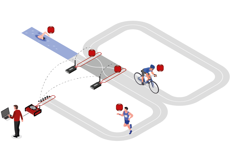
In this mode, the Loop Box activates the transponder, receives its data and sends (repeats) it to a primary system.
This is an easy way to connect several timing points within an area, e.g. a triathlon finish, transition in and transition out. The maximum distance between repeating / receiving devices can be up to 900m depending on conditions.
Note that the Loop Box has an internal buffer for 1000 detections. Even if the connection between Loop Box and the main loop is interrupted, the detections will not be lost: once the connection is recovered, the Loop Box will transmit the buffered detections. Thanks to the precise internal clock of the Loop Box, the detection time will still be correct and precise.
For the communication between devices when using Repeat Mode please note:
- Loop Box and the main loop need to run on the same channel (see Channel ID Setup). It is recommended that you select a fixed channel on the main decoder instead of using the auto mode.
- The main loop that will receive the detections from the Loop Box(es) must have Loop ID 1. This way the Loop Boxes know where to send the data even if several systems are present.
Impulse Mode
The Impulse Mode is the same as Repeat Mode, but the audio output will be used as impulse input that creates a fake detection.
Store & Forward (FW2.6 and above)
This mode only works with the ActivePro and MotorKart transponders, V2 transponders may additionally return less accurate times.
In this mode, when the transponder is activated by the Loop Box, it will create a stored passing on the transponder and additionally send the passing to the device.
For each stored passing an internal timer on the transponder is started which can then later be converted in to a time, the stored passing maintains the loop information of the device which activated the transponder. The internal clock for each stored passing runs for a maximum of 24 hours (passings will be deleted afterwards) and a maximum of 64 passings can be saved.
When the transponder is activated by another active system which is not in Store & Forward or Store mode then the transponder will transmit not only the new passing but also all stored passings.
For the forwarded passing to be received you will need to follow the same guidelines for comunication as per Repeat mode.
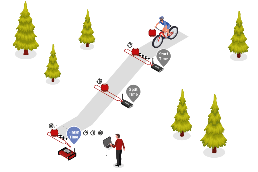
For example for a MTB downhill race, a Loop Box at the start and split could create stored passings on the transponder, and at the finish three detections will be received (start, split and finish).
Should the start or split Loop Boxes be in range of the inish, then these will be received immediately. If, however, the connection drops out during the race, passings will still be stored on the transponder and will then be received at the finish.
When using Store & Forward mode, if you receive both the forwarded passing and the stored passing then the Active system may not store two records in the passings file. For every incoming passing the system checks within the most recent 1,000 passings if it received another passing with the same Wake Up Count. If so, then the later one will be ignored as it is considered a duplicate.
Additionally note that the forwarded passing may have lower accuracy than the stored passing or regular Repeat mode, as the internal calculation and communication prioritises the stored passing.
Store Mode (FW2.5 and below)
Similar to Store & Forward mode, transponders will create a stored passing which can be read out at a later time.
With Store mode on Firmware 2.5 or earlier the passing is not additionally forwarded to the device, only the stored passing is generated.
Loop Box Time
Note that the Loop Box and the ActivePro/MotorKart transponder do have an internal clock, but do not need to have the current time of day. They simply tell the main loop how much time has elapsed since the detection occurred. The main loop will then calculate the detection time by subtracting this offset from its current time.
Receiving Loop Box Data and monitoring the connection using RACE RESULT 12
When using one or more Loop Boxes in Repeat Mode, the detections from several timing points will be received through the base (Loop ID 1) Ubidium or RACE RESULT System with Active Extension or USB Timing Box, and be read in the Timing tab through one single connection.
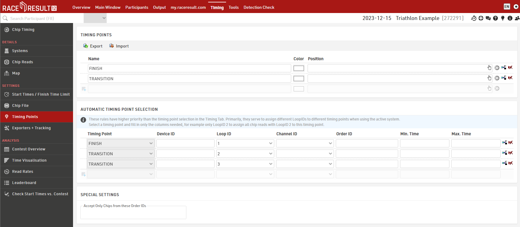
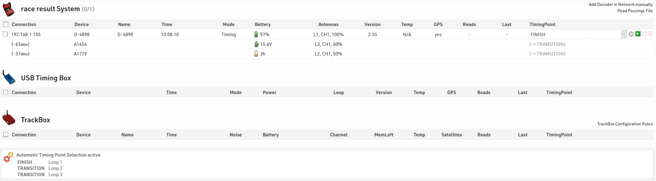
To assign detections from a certain loop to a certain Timing Point in the software, go to the Timing points settings in the Timing tab in your event file, and define the Automatic Timing Point Selection settings. The below screenshots show a typical setup of a triathlon event, the main system at the finish line is set to loop 1 (base), the two Loop Boxes at the entrance and exit of the transition area are set to loop 2 and loop 3 respectively.
In the Chip Timing and Systems section of the Timing tab, the Loop Boxes are listed under the main system they are connected to, with an indication of the signal strength and of the battery status. On the far right, the software displays which timing point the data of the Loop Box will be written in, if an automatic timing point selection rule applies. For the main system, note that you do not necessarily need to select a timing point in the drop down selection menu if you have set up a rule that applies to that channel and loop ID combination. The automatic timing point selection rules have priority over the dropdown selection.
Here is a table indicating the estimated quality of the signal based on the value displayed:
| Quality | Value |
| Perfect (could not be better) | above -65 dBm |
| OK (nothing to worry about) | -75 dBm, ... , -65 dBm |
| Not Great (still working, but could be better) | -85 dBm, ... , -75 dBm |
| Barely Detected (setup should be checked) | below -85 dBm |