Ubidium
You can access Ubidiums' data via an API based on Protocol Buffers / gRPC. They listen on all local interfaces on port 443 and provide a TimingSystem server.
Ubidiums will also be able to connect to remote servers running a very similar API. You will have to implement a TimingServer server therefor.
You can create source code for many languages by translating the provided .proto files using the protoc compiler.
Using our Ubidium SDK can help you to get started with developing your own gRPC client or custom server.
Our SDK provides basic examples of TimingSystem clients and TimingServer servers in several programming languages.
Meanhwile examples in Go, C#, Java, Python and C++ can be found along with a wrapper for C.
All of these can only help you to get started and are all but complete.
You can find both, the .proto files and the examples, attached to this article.
The documentation of the API is provided as comments in the .proto files and here in the knowledge base.
Services
Global messages
USB Timing Box
This document describes how to communicate with a USB Timing Box using the ASCII Protocol. This document is specifically designed for developers who wish to integrate the RACE RESULT USB Timing Box into their software.
This document describes Firmware version 2.4 and up.
Arrows in this document
← indicates data sent from the computer to the USB Timing Box.
→ indicates data replied from the USB Timing Box to the computer.
Quick Start in 3 steps
Open serial port using 19200 BAUD 8N1. Wait 3s before sending first command. Make sure DTR-Line is low.
Step 1) Switch to ASCII-Timing Protocol (only needed in FW 2.4)
← ASCII\n
→ ASCII;00\n
→ \n
Step 2) Pair & Sync computer time and internal time stamp
← EPOCHREFSET;4a3caa45\n
⇅ toggle DTR line
→ EPOCHREFSET;00\n
→ 4a3caa45;0151bcf5\n
→ \n
Step 3) Get passings
← PASSINGGET;00000000\n                       // get passings starting at 0
→ PASSINGGET;00\n                             // command echo, no error
→ 00000000;03\n                               // 3 passings available
→ GLBAS60;0718;01521527;0c;08;9f;1a;0;1;2;00;0\n
→ GLBAS70;04c1;01521536;14;09;9f;1a;0;1;2;00;0\n
→ EMPAL70;047c;0152153b;0e;08;9f;1a;0;1;2;00;0\n
→ \n
Serial Communication
Communication is established via a virtual serial port provided by a built-in USB-serial-converter (FTDI FT232R), with 19200BAUD 8N1. Make sure to have the latest FTDI drivers installed.
PULL Protocol
Your software always initiates any communication by calling a command. The USB Timing Box will immediately respond and then wait for the next call. There is one exception: prewarns. If you enable prewarns, data is pushed without notice (but only if no other command is processing/pending).
 The USB Timing Box only processes one command at a time. If you call a command, you must always wait for the response to finish, before sending the next command.
DTR-Line Reset
It is critical that you actively control the DTR-Line (Data-Terminal-Ready) and set it to LOW/false as default setting at all times. If the DTR line is HIGH/true for more than 500msec, the USB Timing Box will do a hard reset! This is intended behavior and allows a host application to reset the box to a known default state.
Hint: Some serial libraries will require you to specifically switch on DTR-Line handling when opening the connection.
RACE RESULT recommends using a terminal tool like HTerm to try and test the connection by manual commands. Make sure your tool of choice defaults DTR to low. PuTTY for example does not!
Known Issue "NON GENUINE DEVICE"
If you or your customer ever encounter a "NON GENUINE DEVICE" message sent from the USB Timing Box, please be assured that RACE RESULT does only source genuine devices. This problem is caused by an error in the FTDI driver. Please follow the steps here.
Boot Up Process
Bootloader
On power up, the USB Timing Box goes through a bootloader process. For 3 seconds after power up, the bootloader is waiting for instructions to upgrade the firmware. During these 3 seconds any character sent to the box will stop it from booting! This results in a "dead" box with LED continuously on.
 Do not send any data to the USB Timing Box within 3 seconds after power up or reset. It is best practice to wait 3s or until the USB Timing Box issues AUTOBOOT\n indicating, that the bootloader is done.
Debug Interface (FW 2.4)
USB Timing Box FW 2.5 and up automatically switches to ASCII-Timing Protocol. FW 2.4 and earlier boots up in a "debug interface". On FW 2.4 you are required to call ASCII\n to switch to the ASCII-Timing Protocol. Be aware that RACE RESULT does not recommend any use of the debug interface. The behavior of the debug interface can change without notice. On FW 2.5 and up, you can switch back to debug interface by issuing the DEBUG\n command.
Reset
There are two ways to reset the USB Timing Box:
- Pull the DTR-Line HIGH/true for more than >500ms
This does not work in a waiting bootloader state. - Issue a RESET\n command.
It is recommended to use this command for testing purposes only.
The box will never perform a reset on its own.
Test boot up by intentionally resetting the box
← RESET\n
→ rrActive\n        //immediately at power up, LED ON
→ AUTOBOOT\n        //after 3 seconds, LED OFF
← ASCII\n           //not necessary for FW 2.5 and newer
→ ASCII;00\n
→ \n
Time Base
Ticks
The USB Timing Box operates on a 0.28ppm time base, counting 256 ticks per second.
Time Stamps
The USB Timing Box does not know the true date and time. It does not know about leap days or seconds. It has no built-in calendar. All times are internally stored as 32 bit time stamps with 256th of a second resolution. As stored passings can be up to 24 hours old. On startup, the USB Timing Box time stamp starts running from 24 hours worth of ticks to avoid negative passing time stamp values.
Computer Time Reference - EPOCHREF
In order to translate a passing time stamp to a real world computer time, you need to reference the internal time base to your computer time. At the point in time you call EPOCHREFSET and pull the DTR-Line HIGH, you create a synchronized value pair:
ref_time_stamp @ ref_computer_time
Where ref_time_stamp is the internal USB Timing Box time base value at synchronization and ref_computer_time is a value set by your application. Both values are stored as a pair in the USB Timing Box. You can always read this value pair with EPOCHREFGET. If your software or computer crashes, the USB Timing Box will keep the correct event time for you. To convert a pass_time_stamp to a real world computer time, you must calculate:
Computer_Time(pass_time_stamp) =
ref_computer_time + ((pass_time_stamp - ref_time_stamp) / 256.0)
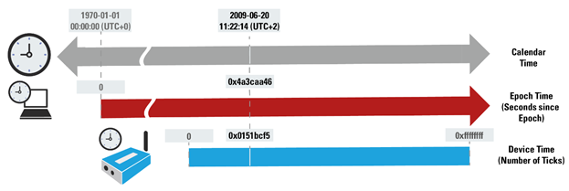
RACE RESULT strongly recommends using the standard UNIX TIME for your computer time reference value. https://en.wikipedia.org/wiki/Unix_time
| Unix Time Epoch | USB Timing Box Time Stamp (FW 2.5 and below) | USB Timing Box Time Stamp (FW 2.6 and up after <CONFSET;B3;1>) | |
| Data | 32bit | 32bit | 40bit |
| Start | 1. Jan 1970 | Last USB Timing Box start up / reset | Last USB Timing Box start up / reset + 7 days |
| Resolution | 1 second | 256th of a second | 2048th of a second |
| Overflow | 19. Jan 2038 | after 193 days of operation | 2^40 / (2048*3600*24*365) = 17 years |
| Init value | 0 | 24*3600*256 = 22.118.400 (24h) | 7*24*3600*2048 = 1.238.630.400 (7 days) |
Commands
Calling a Command
Commands always start with the uppercase name, which can be followed by parameters which are separated by a semicolon and terminated with a newline \n.
Reply
Replies always start with an echo of the command followed by a semicolon and a return code indicating success or error. The next lines contain the response of the call. Every response line is terminated with a single \n newline character. The reply is finally terminated with another \n newline character. It is best practice to wait for a double \n\n new line as indication for the end of the call. \n\n will never be part of the response data.
Parameters and Response Values
All numbers are transferred as hex numbers, without any prefixes (like 0x), in lowercase letters and always with leading zeros.
Return Codes
|
00 |
success, no error |
|
10-1f |
command specific error, see command description |
|
ff |
error unknown command or parameter(s), unless caught by return codes 10-1f |
Step-By-Step Guide
Open the port using 19200 baud, 8N1. Wait for 3s before sending any command after start up.
RACE RESULT Decoder TCP/IP
Hosts use a text-based protocol to communicate with RACE RESULT 4000/5000 Series System's decoders via TCP/IP on port 3601 or via RS232 using a USB-COM-port adapter. By default the RACE RESULT Decoder acts as server, but since protocol version 1.5 a client mode is also available. The default approach for getting passings is pull-based. Since version 1.5 the decoder can automatically push passings to the host as they appear, too.
Quick start/brief example
The following example assumes that you’ve successfully established a connection to the Decoder. You can establish a connection either with your own software or, for testing purposes, using a Telnet client like the one that Windows offers or PuTTY. For the remainder of the document, the following symbols are used:
← denotes commands that you send
→ responses from the decoder.
<CrLf> are the carriage return and line feed characters which needs to be added after every command. (Note: A telnet client will do this automatically when you press the enter key.)
For a complete description of a specific command refer to its individual section.
First set the protocol version to the latest version available at the time you are doing your implementation. That way you can use all available features. The newest protocol version might not be available if the decoder’s firmware is not up to date. Note: Newer (upcoming) firmware versions will always support older protocol versions.
← SETPROTOCOL;2.0<CrLf>
→ SETPROTOCOL;2.0<CrLf>
After start up, the decoder is in Test Mode and will not store passings. To switch to operation mode:
← STARTOPERATION<CrLf>
→ STARTOPERATION;OK;0000-00-00;00:00:00.000<CrLf>
Now passings are saved and the time is running on the decoder. You can query the current time using:
← GETTIME<CrLf>
→ GETTIME;0000-00-00;00:02:12.942<CrLf>
To check the current number of passings:
← PASSINGS<CrLf>
→ PASSINGS;1<CrLf>
This assumes that you have generated a passing on the decoder using a transponder or a marker detection.
To fetch that passing, simply send the number 1:
← 1<CrLf>
→ 1;592;0000-00-00;12:30:12.322;888;4;-52.778000;38cd1c;0;;;;;;;;D-4476<CrLf>
  <CrLf>
Note: You can query multiple passings by calling X:C where X is the first passing that should be returned and C is the max. number of passings that the call will return.
Instead of only querying the current time, you can request extended status information:
← GETSTATUS<CrLf>
→ GETSTATUS;0000-00-00;00:02:39.942;1;11111111;1;50;1;49.721,8.254939;1;0;;;;;;;1;0<CrLf>
You will most probably call the PASSINGS, GETTIME and GETSTATUS periodically and fetch new passings as soon as PASSINGS reports them. After your event has finished you can stop the operation mode so no new passings will be saved when the decoder detects transponders:
← STOPOPERATION<CrLf>
→ STOPOPERATION;OK<CrLf>
Basic commands
Advanced commands
Attachments
Track Boxes
Track Boxes use a Protocol based on simple HTTP communication, this was a design choice to optimise battery life of the devices.
For third-party platforms looking to retrieve data from Track Boxes we recommend using the REST API to load passing and status data since Track Boxes can only send data to a single endpoint.
TrackPing Call
TrackBoxes do a plain HTTP-POST (no HTTPs*) to push their box location and TrackPing data to your server.
TrackBox expects a HTTP-200 reply if your server was able to receive the data. As long as it does not receive a HTTP-200 reply, the TrackPing data will be stored and retried endlessly every 10 seconds. If your server replies HTTP-503 "Service Unavailable" the next call will be delayed for one full minute.
URL/Forwarding
Your server can:
- Be directly called by a track box. The URL of this must be configured on the Track Box manually, check how to Configure Track Boxes. The base part includes every character up to and including the "?". It can be a maximum of 89 characters including the "?".
- Be called by our server in a simple call forwarding scheme. This is used if the data should also be available for time keeping purposes. The user must configure forwarding in RR12 timing module. Be aware, that a HTTP 503 reply to our server will just delay the retry of the current call from our server to yours using expontial backoff. New data from that box and data from other boxes will still be forwarded immediately. If a call is repeatedly answered with a 503 status code for ~24 hours (~30 calls), it will be droped by our server.
Typical Call with moving position and TrackPings
/trackping?v=2&custId=10000&boxId=T-20034&boxType=PTrack&boxName=NikiasV10EU%5FTESTBOX&boxTime=210827T110003Z&boxPos=M,49.05802,008.47133,105&index=1&count=10&dataIndex=0&auth=13953
ZCTAA66;22;-40;15;92832;;;;20;-90;\r
ZCTAA55;22;-42;19;157302;;;;18;-80;\r
ZCTAA53;22;-53;15;113108;;;;17;-77;\r
ZCTAA62;22;-42;21;91281;;;;16;-76;\r
ZBAAA48;15;-71;5;80109;;;;13;-77;\r
ZCTAA66;22;-50;15;92832;;;;11;-70;\r
ZCTAA55;22;-42;19;157302;;;;10;-76;\r
ZCTAA53;22;-63;15;113108;;;;9;-70;\r
ZCTAA62;22;-42;21;91281;;;;6;-50;\r
ZBAAA48;15;-71;5;80109;;;;3;-77;\r
\r
HTTP Post Parameters
| v |
required |
protocol version (currently 2). |
|
| custId |
required |
Customer ID - can be set by the customer to any 6 digit ID. Will normaly be his rr customer ID. |
|
|
boxId |
required |
Serial number of the calling device including the prefix for hardware type. TrackBoxes start at T-20000. |
|
| boxType | optional | Type of hardware that generated this data. Possible values are {ATrack, PTrack, Timing}. Defaults to ATrack if omitted. |
|
| boxName | optional |
Name of the box. Standard names could be START, FINISH, SPLIT, 5K, 10K, HALFM ... can be configured by user. |
|
|
boxTime |
required |
Current time of TrackBox in the moment of calling the http post. |
|
|
boxPos |
required |
Flag,Latitude,Longitude,Altitude of the Box at the moment of calling the HTTP-POST boxPos=U boxPos=S,49.01469,008.52240 boxPos=M,49.01469,008.52240,226 boxPos=T,49.01469,008.52240,226 boxPos=X,49.01469,008.52240,226
Flag: String indicating different information about this trackping GPS location: |
|
| cell | optional |
Current cell ID of TrackBox. Can be omitted if GPS position is available. |
|
|
lac |
optional |
Current network area code of TrackBox. Can be omitted if GPS position is available. |
|
|
index |
required |
Index of this call. Restarts from 1 when Track Box boots. Counts up with every call that a box tries to post to a server (even if then the call is not successful - eg returns HTTP 200). Can be used to reset a "file" logic on server and gaps in index indicate that there have been unsuccessful calls. |
|
| count |
required |
Number of Trackpings in this call | |
| dataIndex | optional | Index of first trackPing in this call. Resets to 0 on reboot. Will be omitted if count==0. Will always be last calls dataIndex + count and unique during runtime of a TrackBox. This can be very usefull to identify copies of data in the case that the box repeats data in a new call because it did not receive an HTTP 200 on the last call. Starts with dataIndex=1 on the first call after boot and first call after change of TrackCallPingURL or CustomerID. | |
| auth | optional | Key to authenticate that the calling box is genuine RACE RESULT equipment. Please contact RACE RESULT for further information. |
HTTP Post Body TrackPing Record
Multiple TrackPings of a transponder are reduced to one TrackPing record. See data reduction algorithm below for more details. Every line represents one TrackPing record and is delimited by a <carriage return>. The last is always an empty line with one <carriage return>. This indicates the end of the call and is the only content sent in an empty TrackPing call.
Each row seperated by semi-colon represents one data field. Data fields can be empty meaning that they default to 0 if they are numeric.
[transponderId];[peakDiffTime];[peakRSSI];[hits];[peakIndex];[flags];[latitudeDiff];[longitudeDiff];[minDiffTime];[minRSSI];[orderID]\r
Data fields:
|
transponderId |
required | Unique Transponder Identifier | |
|
peakDiffTime |
required |
Seconds between the moment of peak RSSI and current boxTime. The higher the value, the more in the past. |
|
| peakRSSI |
required |
RSSI value at peak signal strength in dBm (a value of -55 means -55dBm). |
|
|
hits |
required |
Counter for number of TrackPings collected for this set of data. |
|
|
peakIndex |
optional |
TrackPingIndex of the TrackPing at peak RSSI. This index is counted up and stored inside transponder for every TrackPing sent out. It is unique per transponder and can help to identify unique TrackPings received by multiple TrackBoxes. | |
|
positionFlag |
optional |
Char indicating position information about the Box at the time of recording this TrackPing record |
|
|
peakLatitudeDiff |
optional |
Latitude of TrackBox at the moment of receiving the peak RSSI TrackPing relative to boxPos in 1/100000 of a degree. The more positive the value, the more the TrackPing position was to the north of current boxPos. To get the true latitude of this TrackPing you need to calculate lat = boxPos.latitude + peakLatitudeDiff/100000. | |
|
peakLongitudeDiff |
optional |
Longitude of TrackBox at the moment of receiving the peak RSSI TrackPing relative to boxPos in 1/100000 of a degree. The more positive the value, the more the TrackPing position was to the east of current boxPos. To get the true latitude of this TrackPing you need to calculate lon = boxPos.longitude + peakLongitudeDiff/100000. |
|
|
minDiffTime |
optional |
Seconds between the moment of minimum RSSI and current boxTime. The higher the value, the more in the past. To get the true minimum time of this TrackPing record you need to calculate minTime = boxTime - minDiffTime. |
|
|
minRSSI |
optional |
RSSI value at minimum signal strength in dBm (a value of -55 means -55dBm). |
|
| OrderID | optional | orderID of a Passive Passing |
Optional values can be left empty, but semicolons must always be present to assure future version compatibility. A typical case would be data from a non moving timing system with flags and all following values missing.
HTTP Post Responce Body
A server can call commands on the box by putting them into the HTTP Post Response Body. See status call documentation for formating and possible commands.
Example (Stationary Timing System):
[transponderId];[peakDiffTime];[peakRSSI];[hits];
/trackping?v=2&custId=012345&boxId=D-5061&boxType=Timing&boxName=Start&boxTime=171024T144243Z&boxPos=S,49.01464,008.52243&count=2
224;62.345;-63;55;;;;;;\r
3465;22.123;-64;76;;;;;;\r
\r
Example (Moving->Traveling TrackBox):
/trackping?v=2&custId=012345&boxId=T-20061&boxName=test&boxTime=171024T144243Z&boxPos=M,49.01469,008.52240,226&count=4
ZBAAA48;12;-34;6;79834;M;1;-1;19;-40\r
ZCTAA55;12;-44;18;156766;M;1;-1;15;-60\r
ZCTAA62;16;-72;15;90739;T;1;-1;11;-80\r
ZCTAA53;13;-77;5;112570;T;1;-1;8;-85\r
\r
Example (Moving TrackBox, no new GPS fix at the begining)
/trackping?v=2&custId=012345&boxId=T-20061&boxName=test&boxTime=171024T144219Z&boxPos=M,49.01470,008.52239,225&count=7
ZCTAA66;24;-45;31;92226;X;-10;;18;-50\r
ZCTAA55;23;-33;31;156696;X;-10;;16;-40\r
ZCTAA53;24;-45;39;112501;X;-10;;13;-60\r
ZCTAA62;24;-46;40;90675;X;-10;;13;-50\r
ZBAAA48;23;-41;15;79799;X;-10;;11;-45\r
ZCTAA66;9;-18;17;92254;M;;;9;-18\r
ZCTAA55;10;-8;12;156723;M;;;8;-28\r
\r
Example (Passive TrackBox, no GPS)
/trackping?v=2&custId=10000&boxId=T-20003&boxTime=200129T110044Z&boxPos=U&cell=B876&lac=118D703&index=603&count=8&auth=04883
8787;1.7;-55;3;;U;;;;;12345\r
8788;1.6;-55;2;;U;;;;;12345\r
8789;1.6;-55;2;;U;;;;;12345\r
8790;1.5;-55;3;;U;;;;;12345\r
8791;1.5;-55;2;;U;;;;;12345\r
8792;1.4;-55;3;;U;;;;;12345\r
8793;1.4;-55;2;;U;;;;;12345\r
8794;1.3;-55;2;;U;;;;;12345\r
\r
Example (empty call):
/trackping?v=2&custId=012345&boxId=T-20061&boxName=test&boxTime=171024T144245Z&boxPos=M,49.01469,008.52240,226&count=0
\r
HTTP Post Header
POST HTTP/1.1
Accept: */*
User-Agent: QUECTEL_MODULE
Connection: Keep-Alive
Content-Type: application/x-www-form-urlencoded
*HTTPS/AUTH Parameter
HTTPs is no option for multiple reasons:
Plain HTTP is allowed by most networks around the world.
HTTPs would need additional negotiation leading to increased battery drain. TrackBoxes only have limited capacity and we want it to run for 3 days. It completely shuts down its communication, as long as it is not transmitting anything. For placing a call it connects to the network and disconnect within 100ms again. Communication is what costs energy, it must be done as quick as possible. 
Furthermore: Whats missing in this diagram, is that one also needs to contact the certifying third party server to verify the certificate.
Furthermore HTTPs does not really give us a big benefit as it is actually not authenticating the calling client, but your server. Encryption would be nice, but the data is not really worth anything without context.
We need to make sure not to open up the server for everyone to call and push data. Thats why you can authenticate the calling device using the auth parameter. Contact RACE RESULT to obtain the public key and algorithm with which you check wether the call is coming from a genuine RACE RESULT device or not.
USB Tag Reader
The USB Tag Reader can be implemented using a DLL file specifically written for working with RACE RESULT transponders. If you plan to implement the USB Tag Reader please contact us via support@raceresult.com to request access to the DLL file
NewTagReader
The NewTagReader function is being used to register a TagReader device to the system.
Syntax
int NewTagReader(int vid, int pid)
Params
|
<vid> |
The devices vendor ID |
|
<pid> |
The devices product ID |
The latest version of the TagReader is using 0xe6a as vid and 0x350 as pid.
Return
It will return a unique ID in form of an Integer, which is required to control the device.
TRConnect
The TRConnect function is used to establish a connection to the TagReader with the given ID.
Syntax
int TRConnect(int tagReaderID)
Params
|
<tagReaderID> |
The ID of the device to be connected to |
Return
|
0 |
Connection was successfully established |
| -4 | Connection could not be established |
| -90 | The TagReader with the given ID was not found |
TRDisconnect
The TRDisconnect function is used to disconnect from the TagReader with the given ID.
Syntax
int TRDisconnect(int tagReaderID)
Params
|
<tagReaderID> |
The ID of the device to be disconnected from |
Return
|
0 |
Connection was successfully closed |
| -5 | Connection could not be closed |
| -90 | The TagReader with the given ID was not found |
TRDoReaderAction
The TRDoReaderAction function is used to perform a given action on the given TagReader device.
Syntax
int TRDoReaderAction(int tagReaderID, int action)
Params
|
<tagReaderID> |
The ID of the device to perform the action |
| <action> | Code of the desired action (ref: Available reader actions) |
Return
|
0 |
Action was successfully executed |
| -5 | Error while performing the action |
| -90 | The TagReader with the given ID was not found |
TRSendCommand
The TRSendCommand function is used to execute any command on the given TagReader device.
Syntax
char* TRSendCommand(int tagReaderID, int cmd, char* data)
Params
|
<tagReaderID> |
The ID of the device to perform the action |
| <cmd> | Code of the desired command (ref: Available commands) |
| <data> |
Depending on the chosen command. See documentation: |
Return
|
Success: |
Response of the device for the executed command |
| Error: | The error message received while executing the given command |
TRSetReaderPower
The TRSetReaderPower function is used to set the power level of the given TagReader device.
Syntax
int TRSetReaderPower(int tagReaderID, int powerLevel)
Params
|
<tagReaderID> |
The ID of the device to perform the action |
| <powerLevel> | The desired power level (Min.: 2, Max.: 18) |
Return
|
0 |
Power level successfully changed |
| -7 | Error while setting up the power level |
| -90 | The TagReader with the given ID was not found |
TRGetSerialNumber
The TRGetSerialNumber function is used to read the serial number of the given TagReader device.
Syntax
*char TRGetSerialNumber(int tagReaderID)
Params
|
<tagReaderID> |
The ID of the device to perform receive the serial number from |
Return
|
Success: |
The serial number of the device |
| Error: | The error message received while reading the serial number |
TRGetChipID
The TRGetChipID function is used to read the chip ID of the given TagReader device.
Syntax
*char TRGetSerialNumber(int tagReaderID)
Params
|
<tagReaderID> |
The ID of the device to get the chip ID from |
Return
|
Success: |
The chip ID of the device |
|
Error: |
The error message received while reading the chip ID |
Available commands
| ReadCardData | 0x01 |
| ReaderActionCommand | 0x02 |
| SetReaderParameters | 0x03 |
| ReadWriteEEPROM | 0X0C |
| GetSerialNumber | 0x0D |
| GetModelFirmwareVersion | 0x0E |
| SystemCommand | 0x0F |
| ReadUID | 0x11 |
| WriteKeyToEEPROM | 0X12 |
| ReadDataUltralightNTAG | 0x13 |
| WriteDataUltralightNTAG | 0x14 |
| ReadData | 0x15 |
| WriteData | 0x16 |
| ISO15693Inventory | 0x21 |
| ISO15693ReadBlock | 0x22 |
| ISO15693WriteBlock | 0x23 |
| ISO15693Information | 0x24 |
| ISO15693CComannd | 0x00 |
| MultiTagRead | 0xF0 |
Available reader actions
| RestoreDefaultActionSetting | 0x01 |
| BeepGreenLightOnShort | 0x02 |
| BeepLightOffShort | 0x03 |
| BeepGreenLightOnLong | 0x04 |
| BeepLightOffLong | 0x05 |
| BeepShort | 0x06 |
| BeepLong | 0x07 |
| GreenLightOnLong | 0x08 |
| LightOffLong | 0x09 |
| StopSenseCard | 0x11 |
| StartSenseCard |
0x12 |
| Reset | 0x13 |
Example in C++
This is an example how to use the tagReader.dll with C++
Loading the DLL:
First you need to load the library, using the LoadLibrary function provided by the <windows.h>. This then looks something like:
HMODULE handle = LoadLibrary(TEXT("C:\\Users\\example\\Documents\\tagReaderDLL\\tagReader.dll"));
If the handle holds a value other than NULL, the library was succesfully loaded.
Loading a function:
To use a function provided by the DLL you first need to define it. Therefore you need the return value and the parameters of the function.
An example to call the function "NewTagReader", which returns an integer and uses two integer parameters, looks like:
typedef int(NEWTAGREADERFUNC)(int, int);
To load the function, GetProcAddress is used. It requires the handle and the name of the function you want to load (Note: the function name is case sensitive). this may looks like:
NEWTAGREADERFUNC *pNEWTAGREADERFUNC = (NEWTAGREADERFUNC *)::GetProcAddress(handle, "NewTagReader");
If the value of pNEWTAGREADERFUNC is other than NULL, the function was loaded successfully.
Calling a function:
After loading a function, the function is ready to be called. This may looks like:
tagReaderID = (*pNEWTAGREADERFUNC)(0xe6a,0x350);
A full example to connect to the TagReader and make it beep:
#include <windows.h>
#include <iostream>

using namespace std;

typedef int(NEWTAGREADERFUNC)(int, int);
typedef int(CONNECTFUNC)(int);
typedef int(DOREADERACTIONFUNC)(int, int);
typedef int(GETCHIPIDFUNC)(int);

int main(int argc, char **argv)
{

   HMODULE handle = LoadLibrary(TEXT("C:\\Users\\example\\Documents\\project\\tagReader.dll"));

   if (NULL == handle)
   {
      cout << "Could not load library" << endl;
      return -1;
   }

   NEWTAGREADERFUNC *pNEWTAGREADERFUNC = (NEWTAGREADERFUNC *)::GetProcAddress(handle, "NewTagReader");
   int tagReaderID;

   if (pNEWTAGREADERFUNC)
   {
      tagReaderID = (*pNEWTAGREADERFUNC)(0xe6a, 0x350);
      cout << tagReaderID << endl;
   }
   else
   {
      return -1;
   }

   CONNECTFUNC *pCONNECTFUNC = (CONNECTFUNC *)::GetProcAddress(handle, "TRConnect");
   int connect;

   if (pCONNECTFUNC)
   {
      connect = (*pCONNECTFUNC)(tagReaderID);
      cout << "successfully connected: " << connect << endl;
   }

   DOREADERACTIONFUNC *pDOREADERACTIONFUNC = (DOREADERACTIONFUNC *)::GetProcAddress(handle, "TRDoReaderAction");
   int actionResult;

   if (pDOREADERACTIONFUNC) {
      actionResult = (*pDOREADERACTIONFUNC)(tagReaderID, 7);
      cout << "actionResult is: " << actionResult << endl;
   }

   GETCHIPIDFUNC *pGETCHIPIDFUNC = (GETCHIPIDFUNC *)::GetProcAddress(handle, "TRGetChipID");

   if (pGETCHIPIDFUNC) {
      char *chipID = (*pSENDCOMMANDFUNC)(tagReaderID);
      cout << "chipID is: " << chipID << endl;
   }

   return 0;
}