The timing data (“detections” or “passings”) can be retrieved in four different ways:
- via the Ethernet interface
- via the USB port
- When uploading the data through the internal 2G/3G/4G module, the data can be downloaded from the Internet.
- By accessing the decoder through your browser
Ethernet/Network Connection
The Ethernet connection is the recommended connection type to read out live data from the system during the race. The system can be connected directly to a computer using a standard patch cable or cross-over cable, or be integrated in a local network using a switch or router.
The RACE RESULT System offers two Ethernet ports and both ports can be used to connect to a computer/switch. The additional port can be used, for example, to connect to another RACE RESULT System (pass through). Both Ethernet ports and the RACE RESULT System itself are connected via an internal switch.
The parameters of the Ethernet connection can be defined in the Network menu.
By default, it is set to DHCP so that the system retrieves a dynamic IP address from a router/DHCP server in your network. For race timing it may be better to assign fixed IP addresses to each system. For that, simply turn off DHCP and enter the IP address manually (you can also set the subnet mask, standard gateway and DNS server which will be necessary when the decoder needs to access the Internet, e.g. for a firmware update).
For more information on network configuration see our Networking Guide
USB Port
The USB port serves to save the detection files on a USB stick. This can be done either after the race or live during the race. When plugging in a USB stick, the decoder will show a message that a stick has been detected and will copy all existing passing files to the stick. A separate folder named by the decoder ID will be created on it.
If a USB stick is plugged in during the race, the system will save the new detections every few seconds on the stick. This can serve as an additional backup: theoretically, even if the decoder had burnt down, the passing data is still stored on the USB stick which can be pulled out.
 Please do not remove the stick while the system is in Timing Mode. This may destroy the file system on the stick.
For the data format of the passing files, please refer to Data File Format.
Mobile Upload
The integrated 4G module (previously 2G or 3G) can be used to upload the detection data to a RACE RESULT database in the Internet. The data can then be downloaded from any place with an Internet connection. In other words, this is an easy way to connect remote timing points.
Upload
To upload the detections using the 4G/LTE module proceed as follows:
- Insert your SIM card in the SIM card slot.
- Go to the menu Upload.
- Enter your RACE RESULT customer number and the PIN of your SIM card
- Leave the mobile APN config setting on "auto". Your provider settings will probably be automatically recognized by the decoder. If not, select "manual" and read the sub-section of this article below to find out how to set up your APN.
- Set the option Enabled to yes.
The modem will go through successive connection stages detailed below as well. Once upload is successfully activated, the upload count on the display should match the current detection count.
You can also upload the data via an Ethernet connection with Internet connectivity. If the the decoder has access to the Internet via one of its Ethernet ports, the IP information on the display is marked with an asterisk. The upload feature automatically uses Ethernet when available, and falls back to 4G if the connection via Ethernet is lost.
Mobile Usage
In the second page of the Upload settings you can set the preference for usage of mobile upload.
There are 3 options for mobile upload.
- Fallback - The mobile GSM will only connect if upload is enabled and no internet connection is available via either the ethernet or via USB Wi-Fi adapter. If the connection drops from a preferred source then the module will attempt connection.
- Hot-Standby - The mobile GSM will connect always even if an alternative internet connection is available. If the connection drops from a preferred source the system will immediately switch to this.
- Preferred - The mobile GSM upload will be used at all times regardless of internet connection via either ethernet or USB Wi-Fi adapter.
Upload Target
In the second page of the Upload settings you can also set the upload target for the data.
As of firmware version 2.58, there are 2 options for upload when working with RACE RESULT 12.
- race result - This uploads via TCP protocols for communication with the Timing Module. This also includes an HTTP fallback in the event that the TCP connection is unstable which will also provide data to the Timing Module.
- race result (obselete) - This uploads data to our HTTP server, this will be fully deprecated at the end of 2021 and should not be used.
Download
When using RACE RESULT 12, you can download the passing data in the Timing Module.
To download the data using your own software, please consult Online Storage Communication Protocol.
GSM connection process stages
If a mobile connection is required, the GSM connection process runs through several stages as briefly described below. If it fails in one of the stages it will restart the process from one of the earlier stages.
Note that the decoder will try to connect to a max. of 20 APNs. If manual APN settings are configured, the manual APN will be tried first. If AUTO APN settings are selected and a connection was already successfully established, the last known successful APN settings (for that SIM/SIM network) will be tried first.
| State as displayed | Meaning | Possible cause of failure |
|---|---|---|
| START | Connection process is starting. | |
| IGNITE | Modem is started. | |
| PORT-SETUP1 | Decoder-modem-communication setup. | |
| MODEM-WAIT | Wait until modem is ready. | |
| PORT-SETUP2 | Decoder-modem-communication setup. | |
| MODEM-TYPE | Detect modem type. | |
| SIM-CHECK | Check for SIM. | No SIM inserted/SIM not readable |
| SIM-INFO1 | Get SIM ID. | |
| PIN-CHECK | Check if a PIN is required. | |
| ENTER-PIN | Enter PIN if required. | Less than 2 PIN tries left. |
| SIM-INFO2 | Get provider information from SIM. | |
| WAIT-READY | Wait until modem is ready. | |
| GET-RSSI | Get signal quality. | |
| SEARCH-NET | Searching for networks. | No network available. |
| APN-LIST | Build list of APNs to use/try. | |
| REGISTER | Register for data communication. | No network available. |
| SET-APN | Set one of the APN settings. | |
| DIAL-UP | Establish data connection. | Invalid APN settings tried/SIM not activated/No low level data transmission possible due to bad reception/Provider issues |
| VERIFY | Verify that data can be transmitted and received. | Invalid APN settings tried/SIM not activated/No data transmission possible due to bad reception/Provider issues |
| CONNECTED | Connection is established. |
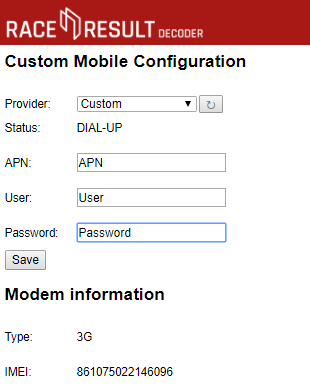
Custom APN Configuration
If your SIM card will not connect using auto-apn then it may require custom APN settings in order to connect.
To enter custom APN settings you should connect to the decoder via the Browser Interface, and open the Configuration tab.
Once inside you will see the option to configure settings for 2G/3G.
The list of providers has a list of already supported APNs or the option for a Custom APN, these APN settings should be provided by your GSM provider, they normally consist of an APN name / URL, a username and password, some APN settings only require the APN name and the username / password can be left blank.
Note that GSM providers may have multiple APN settings depending on which service you have subscribed to.
To store these press save and ensure to switch your decoder to use the Custom 2G/3G APN configuration.
Browser Access
You can easily access the decoder by entering the IP address in your browser, e.g. http://192.168.1.43
In the browser you can:
- Access all (old) passing files. Note that you cannot delete passing files. When the internal memory of 85 MB is full (it can save over 1 million detections), the oldest files will be deleted automatically.
- Access emergency data files. These are created during test mode and are stored automatically when timing is stopped.
- Set the time zone
- Configure upload settings including Custom APN Configuration, upload target and client mode.
- Upload Diagnostics Data
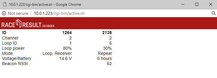
- Check the status of connected Loop Boxes
- Start / Stop Timing mode
Show Active Systems
When connected to an active extension there is an option to view active systems, this allows you to see the status of the active extension and any connected loop boxes. This will open in a new mini window.
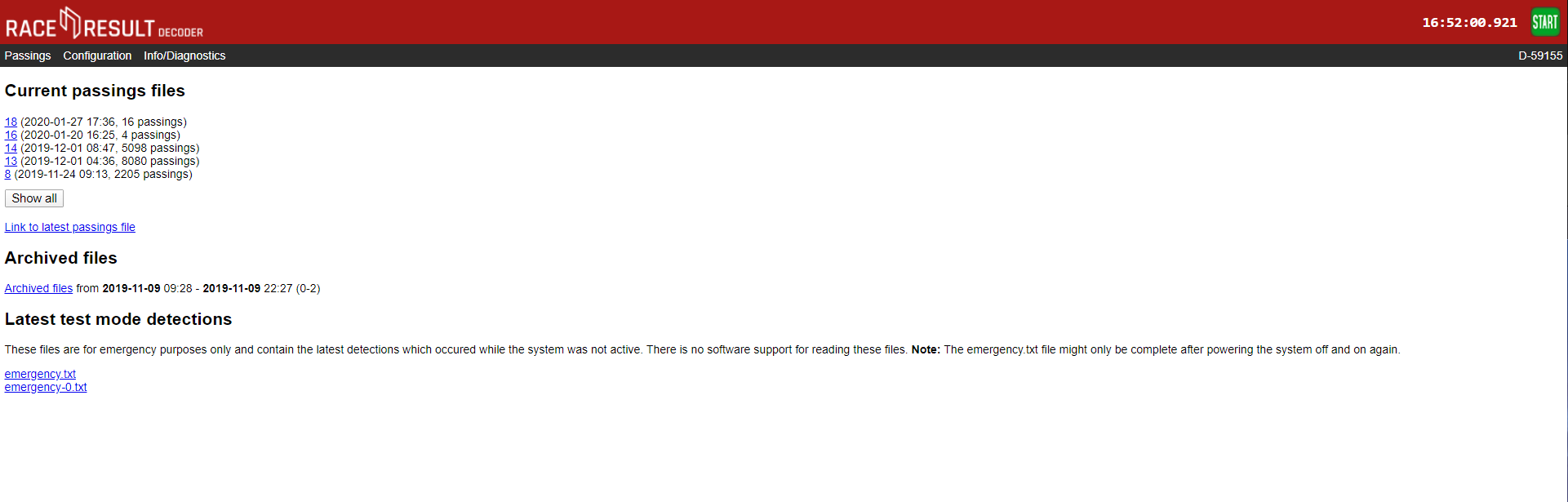
Passings
All passings files on the decoder can be accessed through the browser interface, any non-archived files will be shown immediately, when files are archived they are grouped together by the date range and can be downloaded.
There are 2 emergency files which are also available, these store the last detections from when the decoder was in test mode. emergency.txt is the most recent and emergency-0.txt is older passings.
There is no support to read this directly in to RACE RESULT 12 and so these files should not be relied on for timing.
Configuration
The configuration tab allows for some additional configuration of settings which cannot be achieved through the decoder menu.
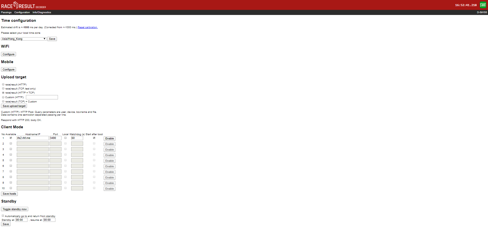
Time Drift
Here you can view the estimated time drift, this is the variation in time that may occur on the decoder, leaving the decoder turned on connected to the internet via ethernet can help to reduce this time drift, resetting the calibration will force the decoder to recalculate the time drift.
Time Zone
The time zone of the decoder can also be changed here using the drop down.
2G/3G
If you need to use custom APN settings for your Sim cards then these will need to be configured through the browser interface. You can also find your Decoders IMEI number from the Mobile Configuration page.
Upload Target
Decoders support upload to both HTTP and TCP, you can choose which method to use or define a custom HTTP target. HTTP upload is used for the Transponder module and Connector software, TCP upload is used for the new Timing Module. We advise using both HTTP and TCP for backup whilst the Timing Module is still undergoing development work.
Client Mode
You can use the decoder as a TCP server to pull data to a client, this is used by some third-party tracking platforms and timing software. There are a maximum of 10 TCP clients which can be configured with the IP address, port number, watchdog and auto-enable.
Find out more in our Developers Section
Standby
Standby is used in some permanent installations where the decoder can be powered down over night to preserve battery, it is not advised to set this for normal events as it could cause premature shut down.
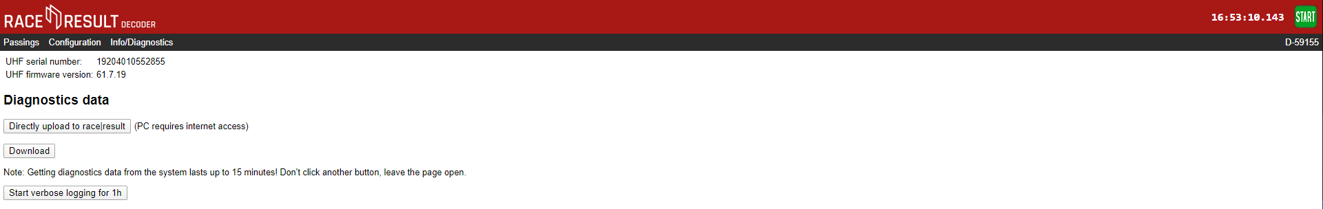
Info / Diagnostics
The info tab shows the UHF reader serial number and firmware version, and also allows you to upload the decoders diagnostics file directly to race result or download it to send to us. This may be required if you experience abnormal behaviour with your decoder during it's use.
Data File Format
The passings in the passing files are stored in the following format:
<PassingNo>;<Bib/TranspCode>;<Date>;<Time>;[<EventID>];<Hits>;<MaxRSSI>;
<InternalData>;<IsActive>;[<Channel>];[<LoopID>];[<LoopOnly>];[<WakeupCounter>];
[<Battery>];[<Temperature>];[<InternalActiveData>];<BoxName>;<FileNumber>;[<MaxRSSIAntenna>];<BoxId><CrLf>
|
<PassingNo> |
Passings record number, starting at 1 for the first passing. |
||||||||||||||||
|
<Bib/TranspCode> |
Bib number of the transponder (or transponder code in case of multi use tags or Active transponders) |
||||||||||||||||
|
<Date> |
Format: yyyy-MM-dd |
||||||||||||||||
|
<Time> |
Time of the detection, format: hh:mm:ss.kkk |
||||||||||||||||
|
<EventID> |
ID of the bib set. The combination of <Bib> and <EventID> is unique for all RACE RESULT Bib Transponders ever produced. |
||||||||||||||||
|
<Hits> |
Number of times the tag was detected. |
||||||||||||||||
|
<MaxRSSI> |
Maximum RSSI value found while determining <Time>. |
||||||||||||||||
|
[<InternalData>] |
This field is only used for internal purposes and is optional. |
||||||||||||||||
|
<IsActive> |
1 if this passing is from an active transponder |
||||||||||||||||
|
[<Channel>] |
Channel ID (1 -> 8) |
||||||||||||||||
|
[<LoopID>] |
Loop ID (1 -> 8) |
||||||||||||||||
|
[<LoopOnly>] |
1, if this detection was generated in Store Mode. |
||||||||||||||||
|
[<WakeupCounter>] |
Overall wakeup counter of the transponder (new transponders start at 10000). |
||||||||||||||||
|
[<Battery>] |
Battery level in Volts. |
||||||||||||||||
|
[<Temperature>] |
Temperature in degrees Celsius. |
||||||||||||||||
|
[<InternalActiveData>] |
Data transmission details. One byte. Lowest three bits: channel busy counter (number of times, the passing could not be transmitted because the transponder could not access the channel). Next three bits: no ACK counter (number of times the passing was transmitted, but no acknowledgement was received.) Seventh bit: 1, if this passing could not be transmitted at all in a previous attempt (="stored passing", old passing), 0 otherwise. Highest bit: 1, if the transponder woke up from deep sleep because of the passing, 0 otherwise. Hint: You can check if a passing is a stored passing using[InternalData] & 0x40 == 0x40 (the seventh bit is set)
|
||||||||||||||||
|
<BoxName> |
Name of the decoder. Defaults to the Device ID. |
||||||||||||||||
|
<FileNumber> |
File number of the file to which this passing belongs. | ||||||||||||||||
| [<MaxRSSIAntenna>] | Antenna number (1..8) which meassured the highest RSSI value. Empty for active. | ||||||||||||||||
| <BoxId> | Device ID | ||||||||||||||||
Client Mode
Client mode is used for outgoing connections to third party software / platforms, it is configured through the decoder Browser Access, client mode can be used to connect to either local TCP/IP servers or online servers. Common uses include third-party tracking platforms and photofinish software integration.
When client mode is enabled the decoder will try to make a connection to the specified server, once connected it allows for the server to send commands to the decoder to pull data and also change settings.
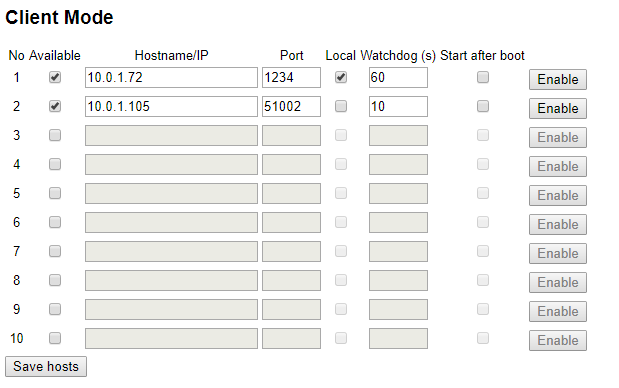
To configure Client Mode you will need the server hostname / URL / IP address and port number, if the server is on the local network then ensure to tick local. The watchdog is the frequency at which the decoder expects commands from the server otherwise it will try to reconnect.
When Client Mode is enabled the upload counters on the screen will cycle between your normal upload counts (Upload / HTTP Up) and TCP Out. TCP Out will show the number of connections which are active through Client mode, if it shows 1 or more then it is connected to the server(s).