La temporización activa ofrece mayor precisión que la UHF ya que utilizan una tecnología completamente diferente para activar el transpondedor y calcular el tiempo, por lo que no se pueden utilizar juntos. Los transpondedores activos contienen una batería y un procesador interno que crean un potente transpondedor con características adicionales que no serían posibles con los transpondedores UHF.
Los sistemas activos no utilizan una serie de antenas sino un cable de bucle que emite una señal electromagnética. La mayor parte del tiempo el transpondedor está inactivo, pero cuando está cerca de un bucle RACE RESULT, la señal de 125 kHz del bucle despertará el transpondedor.
El transpondedor analiza la señal de 125kHz y si proviene de un bucle RACE RESULT, encenderá su microcontrolador que analiza la intensidad de la señal del bucle, calcula el tiempo en que cruzó el centro del bucle y transmite esta información en un 2.4 Canal GHz al decodificador. Cuando el decodificador reconoce que se han recibido los datos, el transpondedor vuelve a dormir.
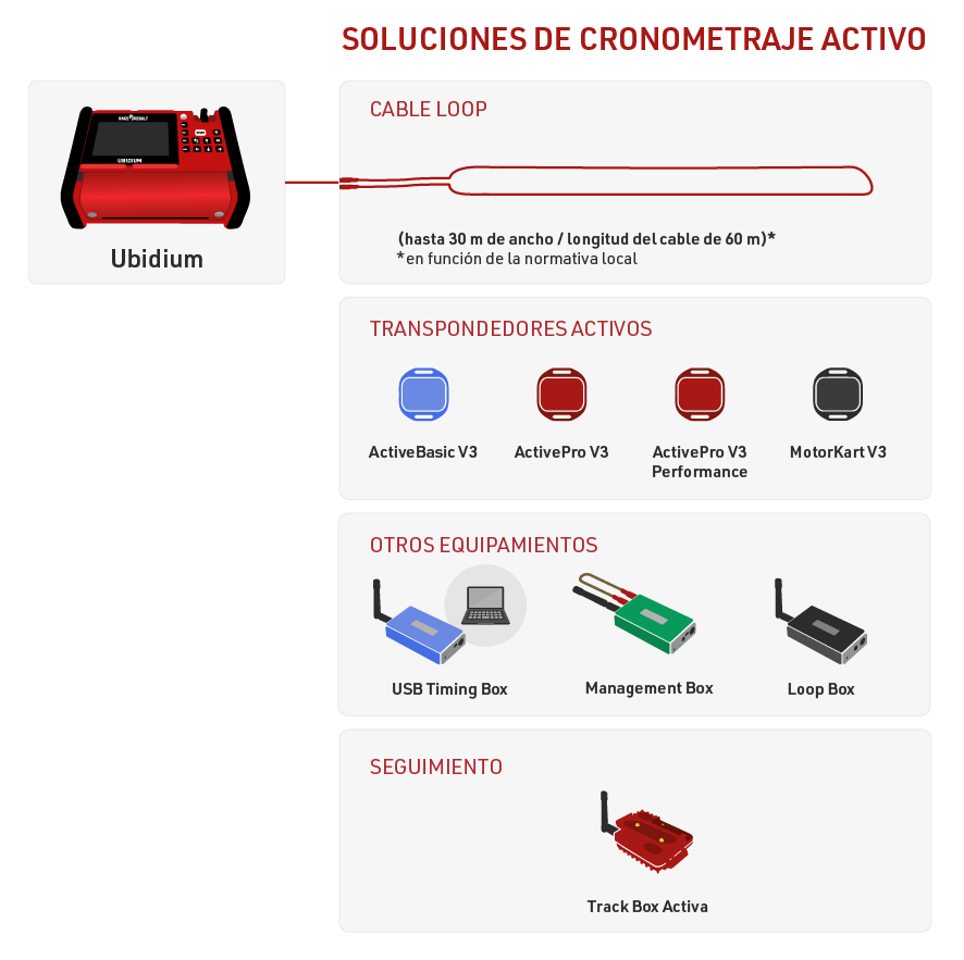
El cronometraje Activo es posible con Ubidium, RACE RESULT Decoder junto con Active Extension o usnado solamente una USB Timing Box.
La Loop Box proporciona flexibilidad adicional a la configuración, se puede ejecutar como un punto de cronometraje independiente, pero debe usarse con uno de los principales sistemas Active para recibir los datos de forma inalámbrica a través de 2,4 GHz o desde Store Mode en el Transponder.
La Track Box Active utiliza 2,4 GHz para recibir seguimientos de transpondedores (cuando están activados) y no depende de ningún cable de bucle adicional. Los Track Boxes contienen un algoritmo diferente para calcular los tiempos y, por lo tanto, ofrecen menor precisión y no deben usarse en áreas donde los participantes pueden permanecer inmóviles durante períodos prolongados de tiempo (como las zonas de transición de triatlón).
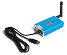
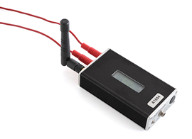
USB Timing Box
La USB Timing Box de RACE RESULT le permite reemplazar cajas decodificadoras con una simple conexión USB a su computadora.
La USB Timing Box se usa mejor para cronometrar eventos deportivos, para escanear etiquetas al recoger el paquete de la carrera o para cualquier otra aplicación: el software de código abierto de la USB Timing Box le permite desarrollar cualquier solución que no tenga nada que ver con cronometraje deportivo.
La USB Timing Box es compatible con nuestra Loop Box, donde la USB Timing Box puede recibir pases de una Loop Box en el modo de repetición. La USB Timing Box no incluye funciones adicionales, como conexión 4G sincronización de hora GPS.
Encender y Apagar la USB Timing Box
Para encender la caja, mantenga presionado el botón hasta que el LED rojo central se apague y se muestre una pantalla de inicio con información sobre el sistema.
Para apagar, presione el botón una vez. La pantalla mostrará lo siguiente:
| press again: OFF |
| hold for config |
Presione el botón nuevamente para apagar.
El dispositivo también se encenderá automáticamente al conectarlo por USB y no se puede apagar.
Al desconectar el USB, se apagará automáticamente si no hay ningún bucle conectado y no se han registrado pases desde su encendido.
Configuración de la USB Timing Box
La USB Timing Box tiene los mismos ajustes que la Active Extension : Loop Power, Channel ID, Loop ID. Adicionalmente, el Modo se puede establecer.
La USB Timing Box se puede configurar presionando el botón durante 2 segundos. La primera de las cuatro configuraciones comenzará a parpadear y se puede cambiar presionando el botón nuevamente. Al presionar nuevamente el botón durante 2 segundos, se confirmará la configuración y se podrá cambiar la siguiente configuración. Para salir de los menús de navegación, continúe presionando el botón hasta que ya no parpadee ningún ajuste.
En este ejemplo, el Loop ID está siendo cambiado:
| Loop█ 1 020% < |
| CH# 8 TIME |
El segmento negro parpadeará para indicar cuál configuración se está cambiando.
USB Timing Box Modes
Timing
In this mode, the USB Timing Box operates as a primary timing device. Times from transponders are received and can be read out via the USB serial connection.
It can additionally receive passings from Loop Boxes in Repeat Mode or Stored Passings from transponders.
Kiosk
Kiosk is intended for when the USB TIming Box should be used for short range applications such as race pack collection or transponder assignments. In Kiosk mode the 2.4Ghz sensitivty is greatly reduced and it is anticipated that only detections from transpodners within ~30 cm of the device will be received.
Note that the 2.4Ghz antenna must be connected in order to use Kiosk mode, without the antenna then the sensitivity will be too low to receive any detections.
Repeat
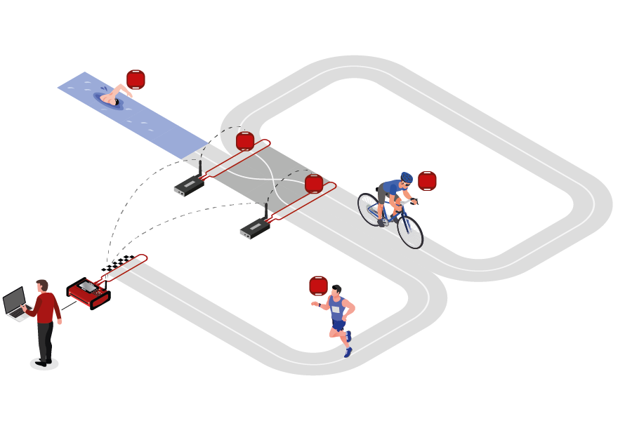
In this mode, the USB Timing Box activates the transponder, receives its data and sends (repeats) it to a primary system.
This is an easy way to connect several timing points within an area, e.g. a triathlon finish, transition in and transition out. The maximum distance between repeating / receiving devices can be up to 900m depending on conditions.
Note that the USB Timing Box has an internal buffer for 1000 detections. Even if the connection between devices is interrupted, the detections will not be lost: once the connection is recovered, the USB Timing Box will transmit the buffered detections. Thanks to the precise internal clock of the device, the detection time will still be correct and precise.
For the communication between devices when using Repeat Mode please note:
- Devices need to run on the same channel (see Channel ID Setup). It is recommended that you select a fixed channel on the main system instead of using the auto mode.
- The main loop that will receive the detections from the devices in Repeat Mode must have Loop ID 1. This way the devices know where to send the data even if several systems are present.
Whilst in Repeat mode USB serial communication is disabled, however the port can still be used for to provide power.
Store & Copy (FW2.5 and above)
This mode only works with the ActivePro and MotorKart transponders, V2 transponders may additionally return less accurate times.
In this mode, when the transponder is activated by the USB Timing Box, it will create a stored passing on the transponder and additionally send a copy of the time to the USB Timimg Box. The passing which is received by the USB Timing box can then be read out via the USB Serial connection as normal.
Additionally note that the copied passing may have lower accuracy than the stored passing or regular Timing Mode, as the internal calculation and communication prioritises the stored passing.
Explicación de la Pantalla
La pantalla de la USB Timing Box puede tener las siguientes indicaciones:
|
La USB Timing Box cuando está en modo Timing y conectada vía USB a una computadora. El icono en movimiento en la esquina superior derecha indica que un cable loop está conectado. La sección inferior derecha de la pantalla parpadeará entre estas dos pantallas. La pantalla superior muestra el indicador de batería. La pantalla inferior muestra el voltaje del USB. Un rango entre 5.0V y 4.5V es bueno. |
||||
|
La USB Timing Box cuando está en modo Timing y con energía de la batería. El "19h" que se muestra en la esquina inferior derecha indica el número de horas de batería restante hasta cero. |
||||
|
La USB Timing Box cuando está en modo Scan y conectada a una computadora. El número "0001" indica el número de etiquetas escaneadas desde que se ha encendido. "ALYFR84" idica el último transpondedor visto por la USB Timing Box. |
Conexión USB
La USB Timing Box se conecta fácilmente con el Módulo del Transpondedor, la Pestaña Cronometraje y el Conector RACE RESULT. Su PC debe tener los drivers USB adecuados para conectarse a la USB Timing Box . Si este no es el caso, consulte Solución de Problemas para obtener instrucciones sobre cómo instalar los drivers de Windows.
Asegúrese de que los softwares TagReaderKeyboard y TagTool no estén abiertos cuando el Módulo de Transpondedor se conecte con la USB Timing Box . Ya que usan puertos COM virtuales para conectarse a la USB Timing Box , no puede conectarse a dos aplicaciones al mismo tiempo.
Actualización de Firmware En Línea
Se recomienda actualizar el firmware cuando haya uno nuevo disponible. Vea Notas de Versiones de Firmware.
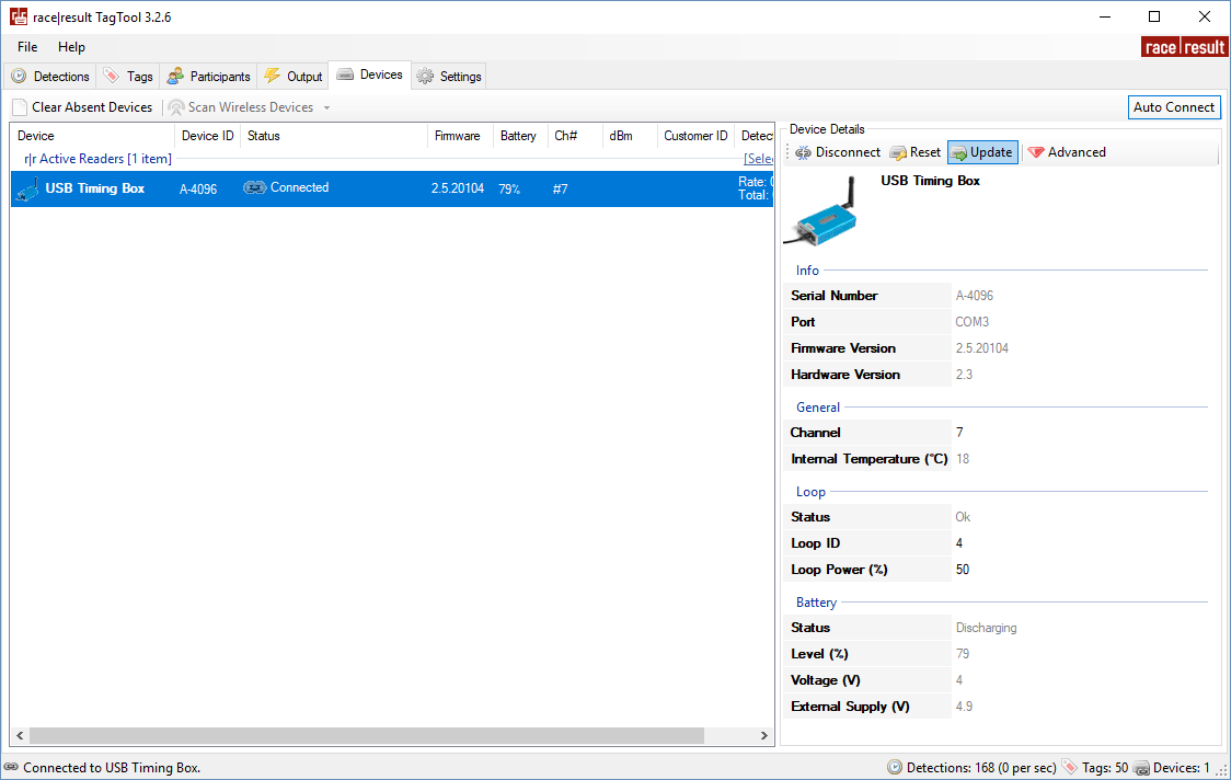
Para actualizaciones de firmware para la USB Timing Box y la Management Box, abra TagTool y conecte su dispositivo, el firmware más reciente de Active Device se incluye en la versión más reciente de TagTool. Una vez que esté conectado, seleccione el dispositivo que desea actualizar, luego haga clic en Update en la ventana Detalles del Dispositivo y seleccione la versión de firmware más reciente (la de valor más alto). Es importante que no desenchufe el dispositivo durante la actualización.
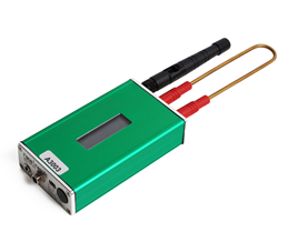
Loop Box
Loop Box es un dispositivo independiente adicional que activa el transpondedor activo, pero no procesa los datos de los transpondedores. En su lugar, los datos que pasan se repetirán a otra caja o se almacenarán en el transpondedor.
En esta sección, la USB Timing Box y la Active Extension serán referidas como el Loop principal.
Encender y Apagar la Loop Box
Para encender la caja, mantenga presionado el botón hasta que el LED rojo central se apague y se muestre una pantalla de inicio con información sobre el sistema.
Para apagar, presione el botón una vez. La pantalla mostrará lo siguiente:
| press again: OFF |
| hold for config |
Presione el botón nuevamente para apagar.
La caja también se encenderá automáticamente al conectarla a una fuente de alimentación externa y no se puede apagar.
Al desconectarla de una fuente de alimentación externa, la caja se apagará automáticamente si no hay ningún bucle conectado y no se han registrado lecturas en el dispositivo desde su encendido.
Configuración de la Loop Box
La Loop Box tiene los mismos ajustes que la Active Extension: Loop Power, Channel ID, Loop ID. Adicionalmente, el Modo se puede establecer.
La Loop Box se puede configurar presionando el botón durante 2 segundos. La primera de las cuatro configuraciones comenzará a parpadear y se puede cambiar presionando el botón nuevamente. Al presionar nuevamente el botón durante 2 segundos, se confirmará la configuración y se podrá cambiar la siguiente configuración. Para salir de los menús de navegación, continúe presionando el botón hasta que ya no parpadee ningún ajuste.
En este ejemplo, el Loop ID está siendo cambiado:
| Loop█ 1 020% < |
| CH# 8 Repeat |
El segmento negro parpadeará para indicar cuál configuración se está cambiando.
Loop Box Modes
Repeat Mode
In this mode, the Loop Box activates the transponder, receives its data and sends (repeats) it to a primary system.
This is an easy way to connect several timing points within an area, e.g. a triathlon finish, transition in and transition out. The maximum distance between repeating / receiving devices can be up to 900m depending on conditions.
Note that the Loop Box has an internal buffer for 1000 detections. Even if the connection between Loop Box and the main loop is interrupted, the detections will not be lost: once the connection is recovered, the Loop Box will transmit the buffered detections. Thanks to the precise internal clock of the Loop Box, the detection time will still be correct and precise.
For the communication between devices when using Repeat Mode please note:
- Loop Box and the main loop need to run on the same channel (see Channel ID Setup). It is recommended that you select a fixed channel on the main decoder instead of using the auto mode.
- The main loop that will receive the detections from the Loop Box(es) must have Loop ID 1. This way the Loop Boxes know where to send the data even if several systems are present.
Impulse Mode
The Impulse Mode is the same as Repeat Mode, but the audio output will be used as impulse input that creates a fake detection.
Store & Forward (FW2.6 and above)
This mode only works with the ActivePro and MotorKart transponders, V2 transponders may additionally return less accurate times.
In this mode, when the transponder is activated by the Loop Box, it will create a stored passing on the transponder and additionally send the passing to the device.
For each stored passing an internal timer on the transponder is started which can then later be converted in to a time, the stored passing maintains the loop information of the device which activated the transponder. The internal clock for each stored passing runs for a maximum of 24 hours (passings will be deleted afterwards) and a maximum of 64 passings can be saved.
When the transponder is activated by another active system which is not in Store & Forward or Store mode then the transponder will transmit not only the new passing but also all stored passings.
For the forwarded passing to be received you will need to follow the same guidelines for comunication as per Repeat mode.
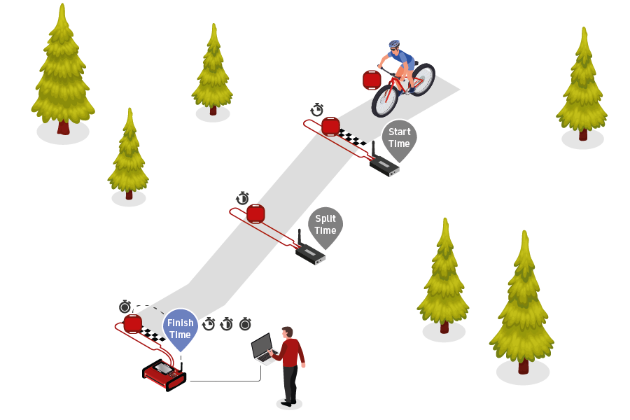
For example for a MTB downhill race, a Loop Box at the start and split could create stored passings on the transponder, and at the finish three detections will be received (start, split and finish).
Should the start or split Loop Boxes be in range of the inish, then these will be received immediately. If, however, the connection drops out during the race, passings will still be stored on the transponder and will then be received at the finish.
When using Store & Forward mode, if you receive both the forwarded passing and the stored passing then the Active system may not store two records in the passings file. For every incoming passing the system checks within the most recent 1,000 passings if it received another passing with the same Wake Up Count. If so, then the later one will be ignored as it is considered a duplicate.
Additionally note that the forwarded passing may have lower accuracy than the stored passing or regular Repeat mode, as the internal calculation and communication prioritises the stored passing.
Store Mode (FW2.5 and below)
Similar to Store & Forward mode, transponders will create a stored passing which can be read out at a later time.
With Store mode on Firmware 2.5 or earlier the passing is not additionally forwarded to the device, only the stored passing is generated.
Loop Box Time
Note that the Loop Box and the ActivePro/MotorKart transponder do have an internal clock, but do not need to have the current time of day. They simply tell the main loop how much time has elapsed since the detection occurred. The main loop will then calculate the detection time by subtracting this offset from its current time.
Receiving Loop Box Data and monitoring the connection using RACE RESULT 12
When using one or more Loop Boxes in Repeat Mode, the detections from several timing points will be received through the base (Loop ID 1) Ubidium or RACE RESULT System with Active Extension or USB Timing Box, and be read in the Timing tab through one single connection.
To assign detections from a certain loop to a certain Timing Point in the software, go to the Timing points settings in the Timing tab in your event file, and define the Automatic Timing Point Selection settings. The below screenshots show a typical setup of a triathlon event, the main system at the finish line is set to loop 1 (base), the two Loop Boxes at the entrance and exit of the transition area are set to loop 2 and loop 3 respectively.
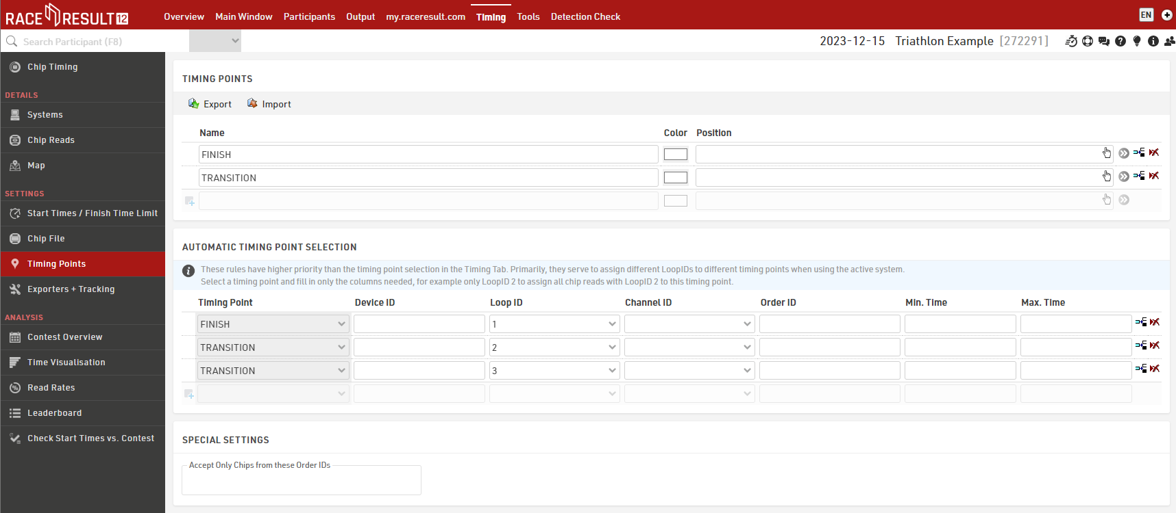
In the Chip Timing and Systems section of the Timing tab, the Loop Boxes are listed under the main system they are connected to, with an indication of the signal strength and of the battery status. On the far right, the software displays which timing point the data of the Loop Box will be written in, if an automatic timing point selection rule applies. For the main system, note that you do not necessarily need to select a timing point in the drop down selection menu if you have set up a rule that applies to that channel and loop ID combination. The automatic timing point selection rules have priority over the dropdown selection.
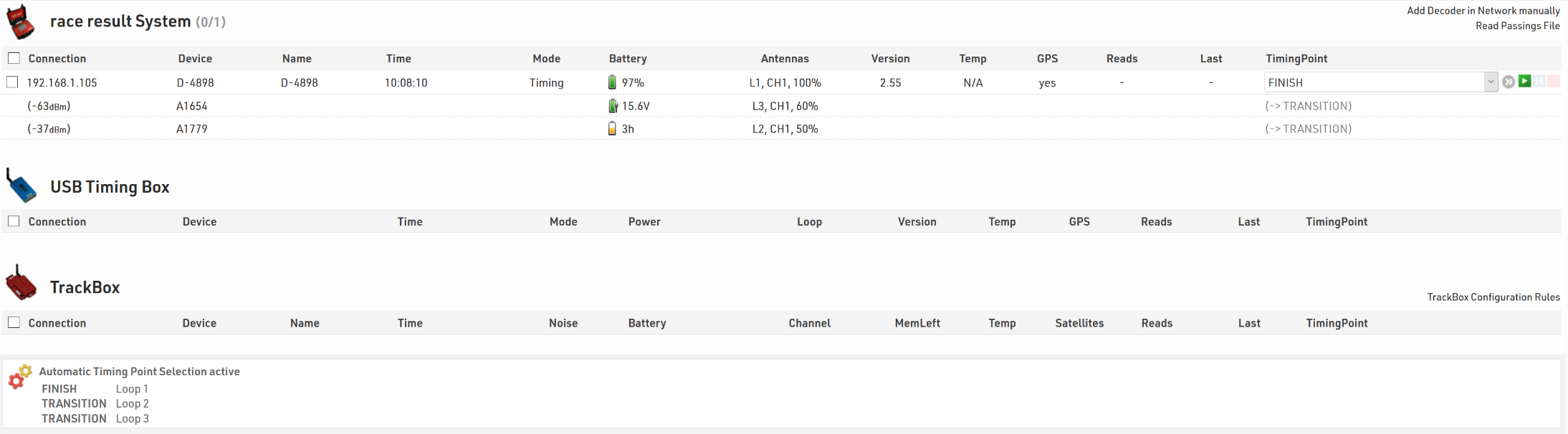
Here is a table indicating the estimated quality of the signal based on the value displayed:
| Quality | Value |
| Perfect (could not be better) | above -65 dBm |
| OK (nothing to worry about) | -75 dBm, ... , -65 dBm |
| Not Great (still working, but could be better) | -85 dBm, ... , -75 dBm |
| Barely Detected (setup should be checked) | below -85 dBm |
Active Extension
The Active Extension connects to the feature port of the RACE RESULT Decoder in order to operate as an active system.
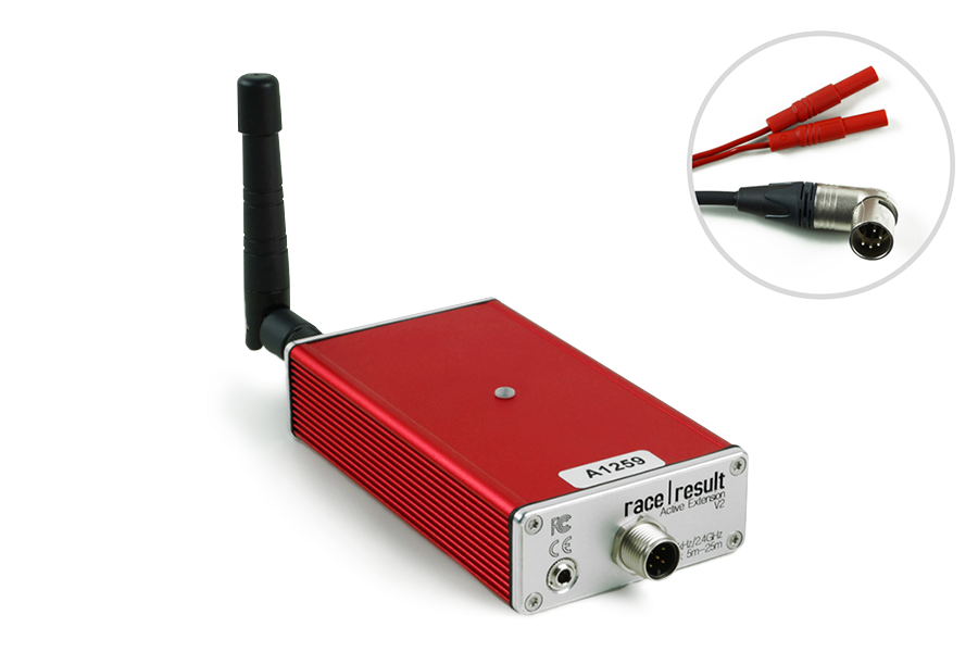
The Active Extension does not have a screen and it entirely controlled by the decoder. When in use the time base of the decoder is managed by the Active Extension which contains a more precise internal clock.
The Active Extension can be used with data cables up to 30m in length, allowing the decoder to be positioned further away from the timing point. It can also be used with the Loop Box to receive passings transmitted by repeat mode, or receive passings which were stored on the transponder.
Management Box
La Management Box es una pieza clave del equipo para administrar eficientemente sus transpondedores activos. También le permite colocar sus transpondedores ActivePro/MotorKart en modo de suspensión, el cual puede ahorrar un 40% de la energía utilizada por los transpondedores.
Turning Management Box on/off
To turn the box on, press and hold the button until the center red LED turns off and a boot screen is displayed with information about the system.
To turn off, press the button once. The screen will display the following:
| press again: OFF |
| hold for config |
Press the button again to turn off.
The box will also turn on automatically when connected to an external power supply, either via USB or the 12 V power connector. When connected to power the device cannot be switched off.
When disconnecting from an external power supply the box will automatically shut down if there is no loop connected and no passings have been recorded on the device since it was started.
Management Box Configuration
The Management Box has several Modes which can be set for different functions, additionally the Loop Power can be adjusted and for Tracking mode the Channel ID and Start/Stop must be set.
The box can be configured by pressing the button for 2 seconds. The first available setting will start blinking and can be changed by pressing the button again. By pressing the button again for 2 seconds, the setting will be confirmed and the next setting can be changed. To exit navigating menus, continue holding down the button until no setting blinks anymore.
In this example, the mode is being changed (currently in Tracking mode):
| Start 100% < |
| CH# 8 █RACK |
The solid segment will be flashing to indicate which setting is being changed.
Management Box Modos
Kiosk (FW2.6 y superior)
El modo Kiosk está pensado para cuando la Managment Box se debe utilizar para aplicaciones de corto alcance, como la recogida de paquetes de carreras o la asignación de transpondedores. En el modo Kiosk, la sensibilidad de 2,4 Ghz se reduce considerablemente y se prevé que solo se recibirán detecciones de transpondedores que se encuentren a unos 30 cm del dispositivo.
Tenga en cuenta que la antena de 2,4 GHz debe estar conectada para utilizar el modo Kiosco; sin la antena, la sensibilidad será demasiado baja para recibir cualquier detección.
Check
El modo de verificación funciona principalmente con TagTool en su computadora. Aquí puede compilar una lista de sus transpondedores, verificar el nivel de batería de los transpondedores y crear un archivo de chip para sus eventos.
Cuando está en modo de verificación, la caja de administración solo enviará una única detección para cada código de transpondedor hasta que se reinicie el dispositivo; sin embargo, tenga en cuenta que el LED del dispositivo puede parpadear varias veces para cada detección.
Este modo puede utilizarse para verificar rápidamente si tiene algunos transpondedores con batería baja en su grupo, escanee los transpondedores y verifique si la pantalla muestra LBAT: XX. En este caso, XX define cuántos transpondedores tienen un voltaje de batería de 2,3 V o menos.
Suspensión
El modo de suspensión profunda se utiliza para activar el modo de suspensión profunda en los transpondedores, lo que reduce su sensibilidad y, por lo tanto, preserva la vida útil de la batería.
Para garantizar que todos los transpondedores estén configurados correctamente, se recomienda organizarlos en bandejas de una cantidad conocida, escanear cada bandeja individualmente y hacer una referencia cruzada con el contador en la esquina superior izquierda de la pantalla.
Para reactivar los transpondedores del modo de suspensión profunda, simplemente se requiere que cualquier dispositivo activo los escanee. En el modo de suspensión profunda, el transpondedor es menos sensible y requiere más toques para reactivarse, por lo que se recomienda hacer esto antes del evento para garantizar que todos los transpondedores se activen.
Track
El Modo Track le permite habilitar y deshabilitar el seguimiento en sus transpondedores.
Seleccione START para activar el seguimiento, o STOP para desactivarlo, en la parte superior izquierda de la pantalla.
Para obtener información completa y mejores prácticas de seguimiento, lea este artículo sobre Activación de Seguimiento de Transpondedores.
Actualización de Firmware
Se recomienda actualizar el firmware cada que haya un nuevo firmware disponible. Vea Versiones de Firmware.
Para actualizaciones de firmware para la USB Timing Box y la Management Box abra su TagTool y conecte su dispositvo, el firmware más reciente se incluye en la versión más reciente de TagTool. Una vez que esté conectado, seleccione el dispositivo que desea actualizar, luego haga clic en Update en la ventana Details del dispositivo y seleccione la versión de firmware más reciente (nombre de valor más alto). Es importante que no desenchufe el dispositivo durante la actualización.
Configuración General
El sistema activo en 2 elementos clave que deber ser configurados correctamente, el cable del loop y la antena de 2,4GHz para la recepción de datos.
Instalación del Cable del Loop
En la mayoría de los casos el bucle del cable se colocará en el suelo y se pegará con una cinta adhesiva o se cubrirá con una alfombra.
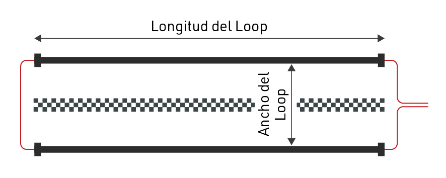
El cable del Loop debe formar un rectángulo con una anchura de entre 30 y 60 cm, con la línea exacta en la que se desea registrar un tiempo posicionado en el centro de la longitud del Loop.
Siempre que sea posible, utilice un Loop de la longitud exacta requerida y evite en todo momento enrollar cualquier axcesi de cable del Loop, ya que esto puede causar interferencias que hagan que los transpondeores no se activen. Los cables del Loop no pueden instalarse en superficies metálicas, éstos inhibirán completamente la señal del Loop, lo que significa que no se generarán pases.
Los Loops pueden enterrarse en el suelo, especialmente para los deportes de motor o en superficies blandas, cuando se hace esto es una práctica común proteger el Loop utilizando algún tipo de tubería.
Ancho del Loop
Si se requiere mayor precisión. el loop debe ser más estrecho, y se debe tener mayor cuidado para configurar el Loops con precisión. Tenga en cuenta que 0.01 segundos significa sólo 5 cm de distancia a 70 km/h. Así que alinear el Loop unos pocos centímetros torcido tendrá un efecto negativo en la precisión.
Un Loop más ancho, por otra parte, dará lugar a una mayor altura de lectura pero puede disminuir la precisión. Esta es la configuración preferida, ya que la mayoría de los deportes que requieren mayor precisión requieren una cámara PhotoFinish para su verificación.
En general, sólo debería hacer el Loop mas estrecho si está seguro de que todos los transpondedores se montarán a la misma altura (por debajo de 100cm o 50cm para el MotoKart) y la velocidad máxima también está por debajo de 100km/h, esto también debería completarse con un Loop Power más bajo para maximizar la precisión.
Puedes ver algunas pautas para el ancho del Loop / potencia del Loop y la altura máxima de detección resultante aquí
Antena de 2.4GHz
La antena de 2.4GHz se utiliza para comunicarse con el transpondedor, así es como el sistema recibe el tiempo exacto de paso del transpondedor. Es fundamental que haya una clara línea de visión entre los transpondedores y la antena de 2,4GHz, y la antena debe utilizarse en todo momento.
En el caso de que la Extensión Activa tenga una visión obscura de los transpondedores, entonces puede ser necesario usar una Extensión de Alcance Activo , esta es una antena de mayor ganancia, ajustada a un cable más largo que permite que la antena se monte más alto y lejos de la interferencia.
Tenga en cuenta que la ganancia adicional de la antena se pierde en la longitud del cable y por lo tanto, el simple hecho de colocar el extensor de alcance en el suelo en la misma posición no tendrá ningún beneficio adicional.
Las antenas deben montarse apuntando verticalmente hacia arriba y mantenerse lo más alejadas posible del metal, ya que esto puede interferir con la señal.
Posibles Problemas de Loop
Los dispositivos activos supervisan el estado del Loop constantemente y pueden informar los siguientes problemas que se mostrarán en la pantalla del decodificador:
Loop Error
El Loop ya no está conectado o se ha cortado. Este error será señalado por el sistema RACE RESULT con un pitido largo.
| Count: 3823 | Time: 11:40:23.323 | ZZZZZ01 |
| File No: 298 | IP: 192.168.1.202 | ZZZZZ01 |
| Upload: off | LOOP ERROR | ZZZZZ01 |
| USB: n/a | Battery: ██████__ | ZZZZZ01 |
Loop Limit
El sistema no puede proporcionar suficiente potencia para el Loop Power seleccionado. El cable es demasiado largo o demasiado delgado. El Loop Power que se ha configurado seguirá siendo entregada, sin embargo, el usuario debe contar con que la altura de lectura se reducirá.
| Count: 3823 | Time: 11:40:23.323 | ZZZZZ01 |
| File No: 298 | IP: 192.168.1.202 | ZZZZZ01 |
| Upload: off | LOOP LIMIT | ZZZZZ01 |
| USB: n/a | Battery: ██████__ | ZZZZZ01 |
Overflow
Los transpondedores se detectan más rápido de lo que pueden ser enviados al decodificador. Active Extension tiene un búfer interno para 1000 detecciones. Si este búfer está lleno, las detecciones se perderán y el decodificador mostrará el error Overflow.
| Count: 3823 | Time: 11:40:23.323 | ZZZZZ01 |
| File No: 298 | IP: 192.168.1.202 | ZZZZZ01 |
| Upload: off | OVERFLOW | ZZZZZ01 |
| USB: n/a | Battery: ██████__ | ZZZZZ01 |
High Noise
El ruido promedio en el canal de 2.4GHz es más alto que el límite determinado, lo que sugiere que debe seleccionar un canal diferente. No afectará drásticamente la precisión de los transpondedores, ya que el canal de 125 kHz se usa para cronometrar el transpondedor. Los transpondedores seguirán intentando enviar sus paquetes durante un segundo después de la detección cuando el canal esté ruidoso u ocupado. Los transpondedores ActivePro y MotorKart almacenarán pases si no pueden enviarlos.
Si la advertencia continúa mostrándose, el usuario debe cambiar el Channel ID del dispositivo.
| Count: 3823 | Time: 11:40:23.323 | ZZZZZ01 |
| File No: 298 | IP: 192.168.1.202 | ZZZZZ01 |
| Upload: off | HIGH NOISE | ZZZZZ01 |
| USB: n/a | Battery: ██████__ | ZZZZZ01 |
Active Settings
The following settings are applied to all Active timing devices, and are important to ensure reliable and accurate operation whilst timing.
Refer to the individual device guides to understand how to set the values on the corresponding device.
Configuración de Channel ID
La comunicación (canal trasero) desde transpondedor al decodificador opera en 2,4 GHz, que es una banda pública mundial que también se usa para muchos propósitos, como Wi-Fi.
Dentro de esta banda, el sistema activo puede utilizar 8 canales de frecuencia diferentes. Cuando el bucle("loop") activa el transpondedor, también codifica la identificación del canal en la señal del bucle para que el transpondedor sepa en qué canal el decodificador está escuchando la respuesta del transpondedor.
Es recomendable utilizar siempre el canal con el menor ruido/interferencia, para ello puedes ejecutar un escaneo de canales en el sistema que estés utilizando. Además, cuando use varios sistemas, debe intentar mantenerlos en diferentes canales, especialmente cuando están muy cerca.
Backup Channels (Canales de Respaldo)
Los transpondedores activos de V2 y superiores (excepto ActiveBasic antes de 2023) usan un canal principal y uno de respaldo para enviar datos de paso a la extensión activa, esto puede ayudar en áreas donde hay mucho ruido en la frecuencia de 2,4 Ghz.
Además, los transpondedores ActivePro V3 Performance admiten la copia de seguridad de Quad Channel Backup.
Configuración de Loop ID
Al activar un transpondedor, el bucle también transmite un ID de bucle. Al transmitir la detección al decodificador, el transpondedor también transmitirá este ID de bucle. De esta forma, varios sistemas activos pueden funcionar en el mismo canal: los decodificadores dentro de un área 'escucharán' las detecciones de todos los bucles, pero solo procesarán las de los transpondedores que hayan sido activados por su propio bucle.
Es una práctica común que sus puntos de cronometraje primarios usen Loop ID 1, este es el designador de que este dispositivo es el punto de cronometraje central.
Cuando se trabaja con Loop Boxes configurados en modo de repetición, es fundamental que el dispositivo que debe recibir esos pases esté configurado en Loop ID 1, esto identifica este sistema como el sistema base para ese canal y solo Loop ID 1 recibirá pases de dispositivos adicionales .
Loop Power
En pocas palabras: cuanto más potencia ponga en el bucle ("loop"), más alto leerá el transpondedor. Tenga en cuenta que con los transpondedores ActivePro V1 / V2 esto también puede resultar en una precisión reducida.
Según el tipo de deporte, elige un valor adecuado para "Loop Power". Por ejemplo, para ciclismo (donde se necesita alta precisión, y el transpondedor se encuentra fijo en la bicicleta, por lo tanto, cerca del circuito -piso-), elija un valor bajo como 20%. Sin embargo, si los participantes usan el transpondedor en la muñeca y pueden terminar con los brazos levantados, elija una potencia de bucle alta como 80% o 100%.
Según los materiales que se encuentren bajo tierra en el punto de sincronización, la altura de lectura máxima con una potencia de bucle del 100 % es de 2 a 2,5 metros. El metal en el suelo reducirá la altura de lectura.
Puede ver algunas pautas para el ancho del bucle/potencia del bucle y la altura de detección máxima resultante here
Datos de detección activa
Con cada lectura el sistema guarda alguna información útil sobre el paso, entender esto puede ayudar a interpretar mejor sus datos e identificar posibles problemas.
Dado que los transpondedores activos contienen más circuitos a bordo y se comunican en el canal de 2,4 GHz son capaces de almacenar y enviar más información con cada pasada, la comprensión de los valores de Hits / RSSI también es ligeramente diferente como se explica a continuación.
- Hits - El número de veces que el transpondedor ha visto el patrón de bucle (que se repite a 150 veces por segundo), hasta la fuerza de bucle más fuerte.
- RSSI (sólo útil para transpondedores V2 y posteriores, no aplicable a transpondedores Active Basic) - Hay dos enlaces de radio implicados, el bucle de 125kHz y la antena de 2,4GHz para la comunicación de datos. Queremos conocer la calidad de ambos, por lo que el sistema informa de dos valores agrupados en una sola cifra.
- X se refiere a la intensidad de la señal recibida en 2,4Ghz, donde -90dBm es la señal más débil y -58dBm la más fuerte
- Y se refiere a la potencia del Bucle donde 1db es la más débil y 16db la más fuerte.
- Loop - El ID de loop del dispositivo que registró el paso
- Channel - El ID del canal del dispositivo que grabó el pase.
- WUC - Wake-Up-Count del transpondedor es el número de veces que el transpondedor ha sido activado por un bucle.
- Batt - El voltaje de la batería del transpondedor, recomendamos retirar los transpondedores con < 2,2v.
- Temp - La temperatura interna del transpondedor.
- SFlag - Estará entre 64 y 127, o será mayor que 192 si el pase se almacenó en el transpondedor o el transpondedor V3 emitió una advertencia.
| Directrices para la fuerza de detección | Hits | 2.4GHz RSSI (X) | 125kHz Loop (Y) |
| Perfecto (no podría ser mejor) | 20..60 | mejor que -75dBm (-58dBm mejor para passing) |
8dB...16dB |
| OK (nada de qué preocuparse) | 10...20 | -80dBm...-70dBm | 6dB...10dB |
| No es genial (todavía funciona, pero podría ser mejor) | 5...10 | -85dBm...-75dBm | 4dB...8dB |
| Apenas se detecta (debe comprobarse la configuración) | 1...5 | -90dBm...-80dBm | 1db...4dB |
Cómo mejorar la calidad de detección:
- 2.4GHz: Asegúrese de que la antena receptora tiene una línea de visión directa con el transpondedor. Si no es así, pruebe a sustituir la antena receptora (elevándola) y/o utilice nuestro extensor de alcance.
- 125kHz: Asegúrese de que hay una línea de visión directa entre el bucle y el transpondedor. Cuando monte el transpondedor en metal/carbón, utilice nuestros soportes para chips para dejar algo de espacio entre el transpondedor y el metal. Compruebe también la anchura del bucle, la potencia del bucle (altura de detección) y la colocación del transpondedor.
Calculation of RSSI Values
Active Box FW 2.4 and older: This value represents the maximum loop strength (Loop_Strength, see below) a transponder saw while recording the passing.
From FW V2.5 and newer: This value represents both, the maximum loop strength and the 2.4GHz strength the passing was received by the Active Box. The 8-Bit Value is bitwise devided XGGGLLLL (x must be ignored, G = 2.4GHz, L = Loop)
- 2.4GHz_Strength = -90 + 4 * GGG [dBm]
2.4GHz received signal strength at Box Antenna where -90dBm is the weakest and -58dBm is the strongest signal - Loop_Strength => 1 + LLLL
Loop Power in positive dB values from 1..16 where 1 is the weakest and 16 is the strongest
Examples:
16: 00010000 => 2.4GHz=-90+1*4 [dBm] and Loop=1+0 => -86dBm/1
77: 01001101 => 2.4GHz=-90+4*4 [dBm] and Loop=1+13 => -74dBm/14
Technical Specifications
Dimensions & Standards |
|
|---|---|
|
Regulatory Conformity and Standards |
EN60950 (safety) CE, RoHS, FCC |
| Operating Temperature | -30°C to 70°C |
| Dimensions | 27mm x 66mm x 117mm |
| Active Extension | |
|
Protection Class (with data cable / antenna connected) |
IP67 -waterproof- |
| Weight | 190g |
| USB Timing Box | |
|
Protection Class (with cable / antenna connected) |
IP52 - water resistant- IP54 with bumper usage |
| Weight | 266g |
| Loop Box | |
|
Protection Class (with cable / antenna connected) |
IP52 - water resistant- IP54 with bumper usage |
| Weight | 272g |
| Management Box | |
|
Protection Class (with cable / antenna connected) |
IP52 - water resistant- IP54 with bumper usage |
| Weight | 274g |
RF Characteristics |
|
|---|---|
|
2.4GHz Channel Frequencies - Main / Backup (Worldwide compliance) |
1: 2.480MHz / 2.405MHz 2: 2.405MHz / 2.470MHz 3: 2.425MHz / 2.465MHz 4: 2.475MHz / 2.440MHz 5: 2.415MHz / 2.445MHz 6: 2.460MHz / 2.430MHz 7: 2.435MHz / 2.455MHz 8: 2.450MHz / 2.420MHz |
| 2.4GHz TX Power |
17.5dBm |
|
Loop Frequency & Data |
125KHz Data packet = Loop ID + Channel Packet Rate: 150Hz OOK-modulation, Manchester encoded, 16-bit anti-false-wakeup pattern |
| Loop Power | 100% = 250mA RMS regulated peak current |
| Loop Cable & Length |
5m - 25m, >0,5mm² standard 4mm banana plugs |
Detections |
|
|---|---|
|
Max Read Range 25% Loop Power 100% Loop Power |
60cm (2ft) 2.5m (8ft) |
| Active Extension | |
|
Transponder Read Rate |
>100 transponders per second burst for 20 seconds >50 transponders per second continuously |
| Internal Data Buffer | 1,000 passings |
| Forewarn Data Delay | 100ms (from entering the loop center) |
| Max Passing Data Delay | 250ms (after loop center) |
| Repetitive Passing Rate Over Loop | 1 per second |
| Clock Stability |
24/1,000th second per day 0.28ppm TCXO calibrated to rubidium frequency standard traceable to NIST |
| USB Timing Box | |
|
Transponder Read Rate |
>100 transponders per second burst for 20 seconds >50 transponders per second continuously |
| Internal Data Buffer | 1,000 passings |
| Loop Box | |
| Transponder Read Rate* | up to 40 transponders per second continuously |
| Passing Transmission Delay | 200ms - compensated |
| Maximum Repeat Range | 900m with direct line of sight |
| Internal Data Buffer | 1,000 passings |
| Management Box | |
|
Transponder Read Rate |
>100 transponders per second burst for 20 seconds >50 transponders per second continuously |
| Internal Data Buffer | 1,000 passings |
*Reduced to account for passing transmission in Repeat mode
Battery & Connections |
|
|---|---|
| Active Extension | |
| Data Cable |
5m (standard) 15m, 30m (optional) |
| USB Timing Box | |
| Battery | 4000mAh, 3.7v Li-Po |
|
Battery Life (Standalone Unit) |
12h - 20h dependent on Loop Power |
| USB 1.1 | 500mA |
| Loop Box | |
|
Battery |
4000mAh, 3.7v Li-Po |
| Battery Life |
12h - 20h dependent on Loop Power |
| Battery Charging |
10v - 15v, 100mA (at 100% Loop Power) |
| AC Power Supply | 110v - 230v, 50 / 60Hz |
| Management Box | |
| Battery | 4000mAh, 3.7v Li-Po |
|
Battery Life (Standalone Unit) |
12h - 20h dependent on Loop Power |
| USB 1.1 | 500mA |
| Battery Charging |
10v - 15v, 100mA (at 100% Loop Power) |
| AC Power Supply |
110v - 230v, 50 / 60Hz |
Serial Port Connection (USB Timing Box & Management Box) |
|
|---|---|
| Bautrate | 19200 bps |
| Stop Bit | 1bit |
| Parity | OFF |
| Databits | 8bits |
| Softflow-Control | OFF |
| Hardflow-Control | OFF |
| DTR-Line | Special Purpose |
Active System FAQs
Minimum distance between two loops
Sometimes you may want to set up 2 loops close to each other to measure speed at a certain point on the course, but it is important to know that a transponder has an internal dead time when it cannot be activated.
As such we suggest as a general guidelines that the minimum distance between 2 loops is the MAX speed in km/h divided by 10. For example if you expect a max speed of 160 km/h (100mph) then a minimum distance of 16m between the 2 loops should be used.
Active System 2.4GHz Frequencies
The RACE RESULT active system communicates via the 2.4GHz frequency, there are 8 channels to choose from each with a unique frequency. Each channel also has a backup frequency, meaning it will switch between the Main and Backup Frequencies which aids transmission in environments where there is high noise.
The backup frequency can only be used by V2 Transponders, when the channel switching of a decoder it set to AUTO it will automatically disable this when a V1 transponder is detected, this will only reset when the system is restarted. This is the recommended setting. Loop Boxes all use AUTO mode by default and this cannot be changed.
| Channel | 1 | 2 | 3 | 4 | 5 | 6 | 7 | 8 |
|
Main Frequency [MHz]: |
2480 |
2405 |
2425 |
2475 |
2415 |
2460 |
2435 |
2450 |
| Backup Frequency [MHz] |
2410 |
2470 |
2465 |
2440 |
2445 |
2430 |
2455 |
2420 |
2.4GHz Test Mode (V2 Boxes FW 2.5 and up only)
The 2.4GHz Test Mode on the USB Timing Box, the Loop Box, and the Management Box allows advanced users to check channels for interference and make sure the 2.4GHz frontend and antenna are working correctly.
To get into Test Mode and check for noise:
- Ensure the device is switched off and has the 2.4GHz antenna connected.
- Press and hold the button, and continue to hold the button until the following screen is shown.
B RSSI=00 LQI=00 CH# 8 NOISE=02 - Press the button to cycle through the channels.
- Ensure that no transponders are activated and no other boxes nearby are operating on the same channel.
- Stay on each channel for at least 3 seconds. Look for the channel showing the lowest value for noise. Noise should show a value below 10.
- To return to normal operation, press and hold the button until the red LED turns on then release the button to resume normal startup.
- For timing purposes, set the box to the channel showing the lowest noise value.
Testing Box 2.4GHz performance (and antenna)
- Boot two boxes in to test mode as above and set them to the same channel.
- Place them aproximately 1m apart on a table.
- Ensure that no other boxes are on the same channel within connection range and no transponders are activated by the boxes.
- Point both the antennas upwards so that they are parallel to each other:
| B RSSI=65 LQI=55 |
| CH# 8 NOISE=33 |
With two V2 boxes, you should see a RSSI Value of at least 60, higher is better. If you see a RSSI value of 60 or better, you know that both boxes and both antennas are working OK.
Noise values can be ignored in this setup.
Testing a Transponder 2.4GHz performance:
Disconnect the loop and hold a transponder against the loop connector terminals to activate it. You should see similar values on the screen.
| T RSSI=75 LQI=55 |
| CH# 8 NOISE=33 |
You should see a RSSI Value of at least 75, higher is better. If you see a RSSI value of 75 or better, you know that the transponder and the box (and its antenna) is working OK.
Noise values can be ignored in this setup.
Testing 2.4GHz performance of an Active Extension:
The active extension does not support this test mode. But you can still test it (and its antenna) with a second box. Set the channel on the decoder to the channel you want to test on and follow the steps for testing a box.
Parameters:
Below is a description of each of the indicators on the screen:
|
Location on screen |
Description |
|
|
B/T |
Top left |
Indicates from what source the values on the screen are calculated from. B = Beacon = Other Box, T = Transponder |
|
RSSI |
Top center |
Received Signal Strength Indicator - measure of received signal power |
|
LQI |
Top right |
Link Quality Indicator (used for internal testing only) |
|
CH# |
Bottom left |
Channel ID |
|
NOISE |
Bottom right |
Noise level of channel |
Active High Noise Warning
A High Noise warning when using an Active Extension is triggered when there is large interference on the 2.4GHz channel which is being used, this can come from common things such as TV cameras, drones, wireless microphones, bluetooth or even public Wi-Fi hotspots. It may also be that the noise warning has been triggered by a Loop Box and so it is important to check your whole surrounding area.
Our 2.4GHz channels can be used alongside other devices on the same frequency, but if these are too strong or transmitting large bursts of data then it can interfere with the detections, with V2 Transponders the interference has been reduced by introducing a secondary backup frequency on all channels.
If possible you should remove the source of the 2.4GHz interference or move it away from your systems, if this is not possible then the channel scanner will show you the best channel to use in your current setup. If you do change channels on your Active Extension then don't forget to also change your Loop boxes and you may also need to change your automatic timing point selection in race result 11.
¿Qué causa "Límite de Bucle"?
El término "Límite de Bucle" (Loop Limit) significa que el Sistema Activo no pudo aplicar la potencia de bucle seleccionada al bucle conectado.
Imagina un auto: pisas el acelerador a fondo, pero estás subiendo una colina y el auto no puede ir más rápido. El auto sabe que quieres que vaya más rápido, pero no puede.
El "Límite de Bucle" se debe principalmente a la inductancia del bucle, que está determinada por:
- Cable del bucle demasiado largo.
- Cable del bucle demasiado delgado.
- Cable del bucle enrollado o envuelto alrededor de metal.
- Demasiado metal alrededor del bucle.
Con nuestro cable estándar de longitud recomendada, rara vez deberías ver un límite de bucle. Sin embargo, con cables más largos, alcanzarás un límite de bucle si configuras el 100%. Esto se debe a límites regulatorios. En bucles más largos, simplemente no está permitido tener una potencia de bucle del 100%.
Detections with Invalid Loop ID / Channel ID
It can happen that an Active Transponder will generate a passing with an invalid Channel ID / Loop ID, these are most commonly received as stored passings due to the cause for triggering them. Normally these invalid passings have just a single hit and there are 3 possible causes that we have identified:
Corrupt Data From Loop
When on the edges of the loop field the data packet received by the transponder can be corrupt, this results in the Transponder storing a passing with the incorrect Channel / Loop ID and a single hit. This was fixed in V2 transponders from November 2017, the new configuration requires 2 hits for a valid passing.
Participants Standing on Loops (Swim Starts)
The most common time this happens is during rolling swim starts when participants are stood directly on or near the loop for long periods of time. This results in similar corrupt data packets as above which would normally be ignored but due to the rapid consecutive detections the transponder may incorrectly store an invalid passing. This can happen to any ActiveTransponder
External Interference
The 125kHz channel is not unique to RACE RESULT transponders, and transponders may sometimes be activated by external electrical interference such as power cables and store a passing, which could be from the day before. This rarely happens to new V2 transponders due to the new configuration but can happen to any transponder if the interference is strong enough to cause multiple hits.
Solutions
If you have older ActivePro V1 Transponders we offer a trade-in program to upgrade to V2 transponders which eliminate most of the invalid passings.
Your decoder has an option to discard all stored passings, if you are not working with stored passings then you could chose to discard stored passings, as these issues are always reported as stored passings then they will be discarded. Warning: You may lose valid detections which have been stored by the transponder which could not be transmitted directly to the Active Extension or Loop Box.
In firmware version 2.26 we introduced an option to discard all passings below X number of hits. We have found that nearly all invalid passings are reported with a single hit, so setting this to discard all passings below 2 hits can solve this, you can also set the value higher if you are seeing lots of invalid passings with more than 1 hit. WARNING: This will discard ALL passings with less than X hits, so if you do have valid detections with a single hit they will be lost, but if you have passings with low hits then you should check your setup as a single hit suggests there is a problem with the loop setup.
USB Device Errors
In the event your USB device (USB Timing Box or Management Box) is not recognised by Windows it may be necessary to manually install the drivers. This is not normally required, the drivers should be automatically installed, but in particularly old devices an error with the FTDI chip the firmware may not be correctly recognised or may be registered as "NON GENUINE DEVICE".
It is necessary to first completely uninstall the drivers before installing new ones so follow the below instructions accordingly and do not connect your USB device until instructed.
- Download CDM Uninstaller from FTDI
- Unzip the contents and right click CDMUninstallerGUI.exe and select Run as Administrator
- In the GUI ensure that Vendor ID is set to 0403 and delete the Product ID.
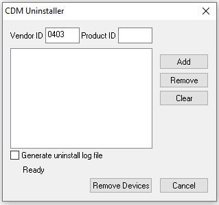
- Click Add and you should see a new item listed as below
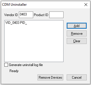
- Now click Remove Devices which will now uninstall all drivers for FTDI converters
- Once this is complete then restart Windows
- Download FTDI Drivers
- Unzip the folder and run the file labelled setup.exe
- Follow the install wizard to install drivers
- Once complete you can connect your USB Device and Windows will now install this using the correct drivers.