
RACE RESULT Ubidium is the most advanced timing solution available on the market, capable of handling both Active and Passive (UHF) timing from a single system.
The Ubidium system is the core of Ubidium and is used to receive data from a range of different timing connections, such as Active Loops, Ubidium Ground Antenna or Impulse Devices, to generate passing data based on the highly-precise on-board clock.
System
The Ubidium System contains the main computing logic and interface for timing with Ubidium.
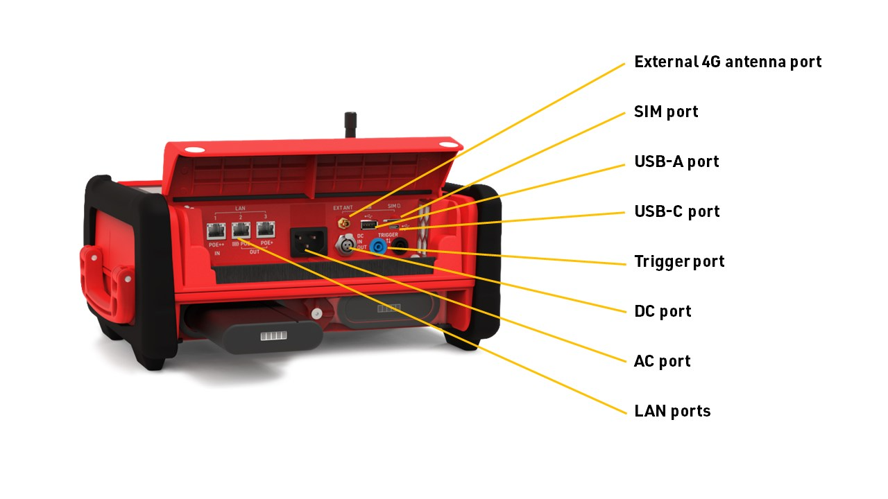
The system integrates all the components required including batteries and power management, the user-interface with display and keypad, 4G / LTE modem, ports for networking and connectivity, timing connectors and more. No external accessories are needed with Ubidium.
Ubidium stores all data on it's built-in memory, this can then be accessed by scoring software, such as RACE RESULT 12, or uploaded directly to a cloud-based server.
The system ensures uninterrupted operation as it runs independently from any other computer or external power supply.
System Components
Ubidium is an entirely self-contained unit, with all the required components accessible directly on the exterior of the shell. The system is designed to ensure all components are protected from water ingress / damage, and does not require any additional cover or lid.
The system is primarily constructed from a highly durable PLASTIC TYPE, designed to withstand the, sometimes, harsh conditions of sports events.


The base of the system features recessed text "THIS SIDE DOWN" and the system should always be setup accordingly to prevent water ingress. Additionally on the base are 4 mounting screw holes for permanent installations, if mounting to a wall then this should be done with the front side facing down.
Ubidium contains an active ventilation system which will be triggered in hot temperatures or in high humidity environments to prevent the formation of condensation on sensitive components.
A handle on the left side can be used to carry the system.
Power & Battery
Ubidium contains a power management system which is used to charge the batteries and also ensure the system operates without interruption even when power sources are changed.
Some power connectors can also be used to provide a power output to power secondary devices.
Startup Process
To power on Ubidium, firmly press and hold the power button until the status LED illuminates green.

Ubidium will now commence the startup process, during this time it will load existing passings from the system and search for a GPS signal. Additionally if the system is set to enable a cloud connection during startup then it will begin to attempt to connect via any available network connection.
Pressing the Start button will skip waiting for any additional jobs.
Once the Startup process is complete, skipped, or if the timeout is reached, Ubidium is ready to begin timing and will automatically start recording all passings.
To turn off the system press the power button and then again when prompted to confirm the shutdown.
Note that even in an powered off state Ubidium will show the current battery state on the display, the power drain in this state is minimised so should not impact negatively on the battery life of the system.
User Interface
The main screen of the system when powered on shows the system time, some fixed system information, the available menu items and some additional information about either the current timing status, network or passing information.

The top row contains the system name and current battery status, the top and bottom display a preview of the next / previous timing information screen.
Battery Status
The current charge level of each battery is shown.
An arrow indicates the charge status for each battery
 |
Battery is charging Time remaining until fully charged |
 |
Battery is discharging Time remaining until empty |
 |
Battery is not currently in use |
Text Input (With Keyboard)
Settings which accept a text input will open a keyboard when editing the setting.

The keyboard can be controlled using the keypad on the device. If connected to the same network as Ubidium or to the system Access Point you can scan the on screen QR code to access the system browser interface which will also provide a text input to directly edit the text using your device.
Tiempos
Firmware Updates
Ubidium firmware updates are automatically downloaded and applied to all systems. When a new version is released, it will be rolled out gradually to systems with increasing availability from the date of release.
When an internet connection is available via either ethernet, Wi-Fi or external SIM card, Ubidium will automatically check for a firmware update every 10 minutes, and will download this update in the background.
When an update is downloaded a prompt will appear on the screen prompting to restart the system to enable the update. If this is cancelled the system will still operate as long as it is switched on and will switch to the new update next time the system is powered on.
In the system Maintenance settings you can choose to whether the system should only download critical updates, or all updates, when connected via external SIM card in order to limit data usage on your SIM card.
It is not possible to completely disable updates for a system.
Technical Specifications
Safety Regulations & Compliance
General Safety Responsibilities
To maintain this condition and to ensure safe operation, the user must observe all instructions and warnings given in this operating manual.
Applicable local and national safety regulations and rules for the prevention of accidents must be observed in all work performed.
FCC Statement
FCC 15.21
Changes or modifications not expressly approved by the party responsible for compliance could void the user’s authority to operate the equipment.
FCC 15.19
This device complies with Part 15 of the FCC Rules. Operation is subject to the following two conditions:
(1) This device may not cause interference.
(2) This device must accept any interference, including interference that may cause undesired operation.
IC Statement
RSS GEN Issue 5
This device contains licence-exempt transmitter(s)/receiver(s) that comply with Innovation, Science and Economic Development Canada’s licence-exempt RSS(s). Operation is subject to the following two conditions:
(1) This device may not cause interference.
(2) This device must accept any interference, including interference that may cause undesired operation of the device.
Cet appareil contient des émetteurs / récepteurs exemptés de licence conformes aux RSS (RSS) d'Innovation, Sciences et Développement économique Canada. Le fonctionnement est soumis aux deux conditions suivantes:
(1) Cet appareil ne doit pas causer d'interférences.
(2) Cet appareil doit accepter toutes les interférences, y compris celles susceptibles de provoquer un fonctionnement indésirable de l'appareil.
Warnings and Cautions
The following alerts are used in this manual:
- WARNINGS alert users of potentially dangerous situations.
- CAUTIONS alert users of potential equipment damage.
Warnings and cautions are indicated by:
- the text WARNING or CAUTION,
- a description explaining the hazard and how to avoid it,
- an icon:

Where to Operate the System
The RACE RESULT Active System uses universal frequencies that can be used globally.
Ground Antenna
The Ubidium Ground Antenna is the most advanced antenna for sports timing, and can only be used with the Ubidium System.
The standard configuration consists of 6 segments of 77cm each, giving a length of 4.6 m / 15 ft, and each segment contains an individual Ubidium Antenna Element.
The ground antenna can be shortened to a minimum of 2 segments (1.5 m / 5 ft) or extended up to a maximum of 30 elements (23 m / 75 ft).
Setup Guidelines
The following guidelines describe the correct setup of your Ubidium Ground Antenna to ensure maximum performance and prevent damage to the components.
Additionally, you should be aware of the setup precautions to further optimise the performance of the system.
Connecting to the System
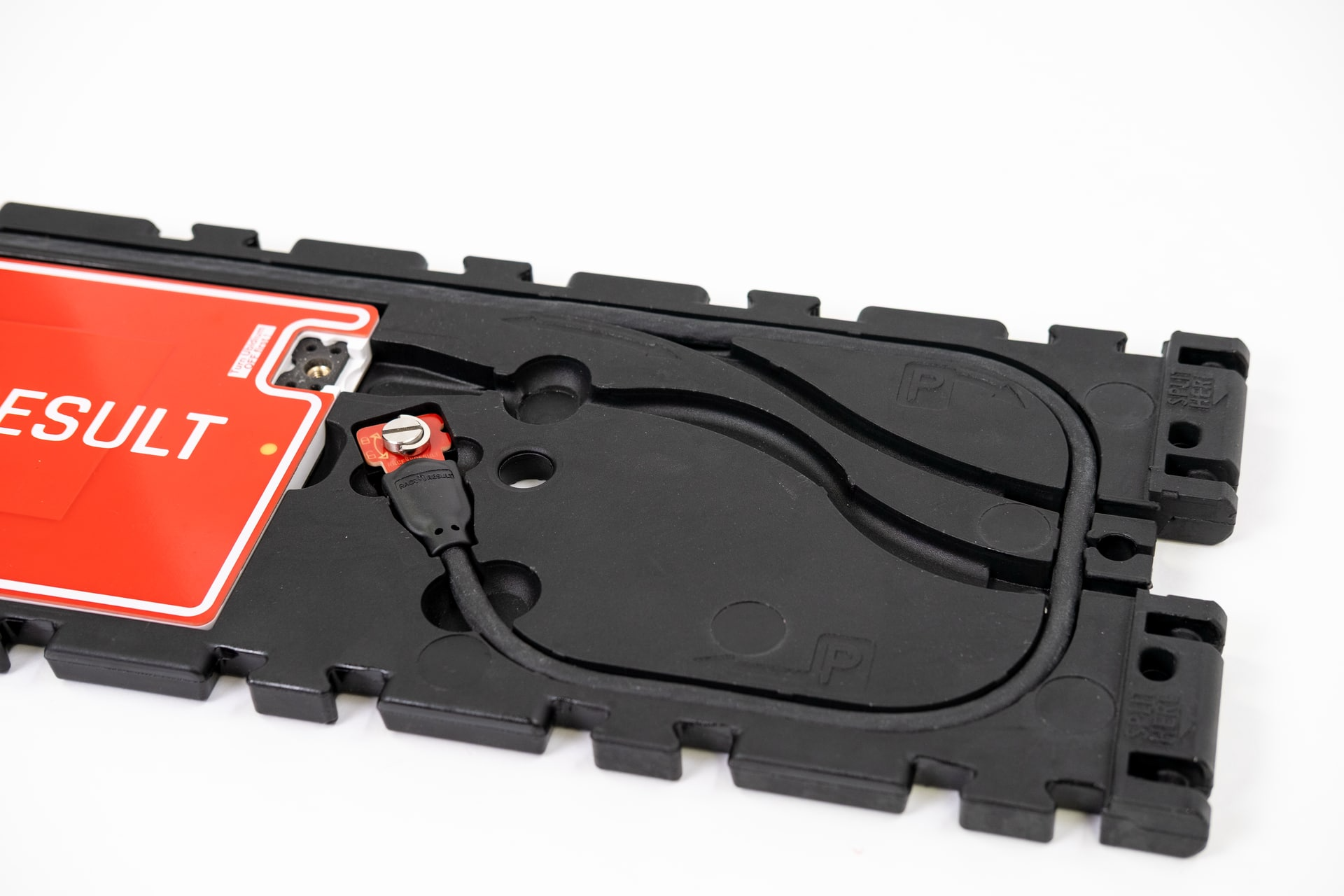
A single connector is used to connect the Ubidium Ground Antenna to the Expansion Port of the Ubidium System.
It is recommended to only connect or disconnect the Ground Antenna when the Ubidium System is powered off.
To connect the Ground Antenna to the Ubidium System, first open the rubber port cover from the Expansion Port and align the red marker on the outer sleeve of the connector with the red marker on the Expansion Port. This will also align the guide pins on the metal sleeve of the connector.
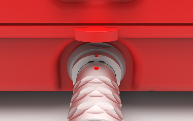
Firmly push the connector in until it clicks in to place, if the connector is correctly inserted it should not be loose inside the Expansion Port.
To remove the Ground Antenna Connector from the system pull on the ridged section of the outer metal sleeve which will release the catch, allowing you to completely remove the connector.
You should always push and pull the connector straight in or out, and at no point should you attempt to twist the connector inside the Expansion Port as this may damage the internal pins.
Components
The Ubidium Ground Antenna is comprised of five key components.
- Black Plastic Base
- Red Plastic Cover
- Ubidium Antenna Element
- Ubidium Connector Cable
- Ubidium Interconnecting Cables
Each component has been carefully designed for maximum performance when used as part of the Ubidium Ground Antenna.
Adding or Removing Segments
The Ubidium Ground Antenna can be shortened down to a minimum of 2 segments (~1.5 meters / ~5 ft) or extended up to 30 segments (~23 meters / ~75.5 ft).
The antenna is designed to be extended or shortened by an even number of segments at a time, the intended splitting points are labelled on the black plastic base of each segment. It is possible to add or remove single segments however this requires additional care and consideration.
Adding or removing segments can be done by opening just 2 individual segments, there is no need to open all the entire length of the antenna.
IMPORTANT: Before adding or removing Antenna Elements - ensure that the Ground Antenna is not connected to an Ubidium System or that the System is shut down.
Opening / Closing The Ground Antenna
To add or remove segments to the Ground Antenna you will need to remove the red plastic covers from the segments at the splitting / joining point.
To remove the covers, lift one edge until the Snap-In buttons release, it should be possible to remove the covers without great force.
Once finished, you must ensure that the covers are correctly fitted to ensure the performance of the system.
To ensure correct fitment, first align the covers and starting on one side push down on the cover to fit the guides joints together then repeat on the opposite side. At the end of each segment it can help to lift the corner of the cover as you are pushing down.
Once the guide joints of both sides are fitted together, start from the middle of the cover and push down moving towards the ends to secure the Snap-In buttons.
Cable Routing
The cabling of the Ubidium Ground Antenna is designed to create 2 unique strands of antennas, to achieve this each interconnecting cable skips one antenna element to connect to the second following element.
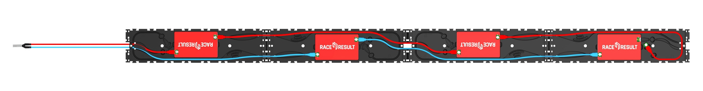
Here the two strands are color-coded red and blue.
The red strand connects to the 1st and 3rd antenna elements and is then in the parking position on the 4th segment.
The blue strand connects to the 2nd and 4th antenna elements, whilst the next blue interconencting cable would be in the parking position of the 5th antenna element to be connected.
Extending the Ground Antenna
To extend the Ubidium Ground Antenna, open the last segment of the existing section and one end of the section to be joined.
Align the 2 sections and connect them using the black plastic hinges, there should be 4 slots to join with hinges.
Remove the interconnecting cables from the parking position on each segment, the coupling joints from each interconnecting cable should be connected to the Antenna Element of the opposite section. Start by gently pushing the plates in to the coupling joint and screw these in by hand to avoid damage to the threads. Once secure then they should be tightened with a screwdriver to ensure they do not come loose.
Only after fitting and securing the coupling joints should you run the cables through the cable channels of the black plastic base, this ensures that there is no additional strain on the coupling joints. The cable channels contain additional slots for slack cable if required.
Shortening the Ground Antenna
To shorten the Ubidium Ground Antenna, open the segments either side of the splitting point.
Start by unscrewing the last coupling joint at the splitting point of the last Antenna Element which will be kept. Similarly unscrew the first coupling joint on the first Antenna Element of the section which is being removed.
The short section of excess cable from each section should be then fitted in to the labelled parking position of the base. This must NOT be looped back and connected to the Antenna Element of the same segment.
To separate the hinges, lift one of the mats to slightly overlap the other and use a slotted screwdriver or similar narrow blunt object to push the hinges out of the joint.
Parking Position
The last interconnecting cable, which will run from the second-last Antenna Element, must not be connected to the last Antenna Element of the same section. This can cause irreparable damage to both the Ubidium System and Antenna Elements.
At the intended splitting point of each segment there is an additional cable channel which runs around the perimeter of the segment with an additional cutout for the coupling joint to be slotted in to. This is additionally labelled with "P" to indicate the parking position.
Removing Single Segments
If removing a single segment from the Ubidium Ground Antenna then the joint will not be a designated splitting point and the base will not contain an additional parking position for the excess cable.
In this situation it is recommended that the additional interconnecting cable is removed from the system to prevent damage, it must not be connected to the last Antenna Element.
Regulatory Information
Human RF Exposure
To comply with exposure requirements of the EU, US, Canada and Japan, this device must be operated at a minimum distance from all persons of at least 30cm/1ft.
Radio Transmitter (FCC Part 15)
This device complies with part 15 of the FCC Rules. Operation is subject to the following two conditions: (1) This device may not cause harmful interference, and (2) this device must accept any interference received, including interference that may cause undesired operation.
Radio Frequency Interference Requirements - FCC
Changes or modifications not expressly approved by the party responsible for compliance could void the user’s authority to operate the equipment.
This equipment has been tested and found to comply with the limits for a Class B digital device, pursuant to part 15 of the FCC Rules. These limits are designed to provide reasonable protection against harmful interference in a residential installation. This equipment generates, uses and can radiate radio frequency energy and, if not installed and used in accordance with the instructions, may cause harmful interference to radio communications. However, there is no guarantee that interference will not occur in a particular installation. If this equipment does cause harmful interference to radio or television reception, which can be determined by turning the equipment off and on, the user is encouraged to try to correct the interference by one or more of the following measures:
Reorient or relocate the receiving antenna. Increase the separation between the equipment and receiver. Connect the equipment into an outlet on a circuit different from that to which the receiver is connected. Consult the dealer or an experienced radio/TV technician for help.
Radio Frequency Interference Requirements - Canada
RSS GEN Issue 5:
This device contains license-exempt transmitter(s)/receiver(s) that comply with Innovation, Science and Economic Development Canada’s license-exempt RSS(s). Operation is subject to the following two conditions:
(1) This device may not cause interference
(2) This device must accept any interference, including interference that may cause undesired operation of the device.
Cet appareil contient des émetteurs / récepteurs exemptés de licence conformes aux RSS (RSS) d'Innovation, Sciences et Développement économique Canada. Le fonctionnement est soumis aux deux conditions suivantes:(1) Cet appareil ne doit pas causer d'interférences(2) Cet appareil doit accepter toutes les interférences, y compris celles susceptibles de provoquer un fonctionnement indésirable de l'appareil
Statement of Compliance - EU/ETSI
race result AG hereby declares that this radio equipment is in compliance with Directives, 2014/53/EU and 2011/65/EU.
Guía de Inicio Rápido
Tu Nuevo Sistema Ubidium
Dentro de tu paquete encontrarás los siguientes elementos:
- Sistema UBIDIUM
- 1 x Batería Ubidium de 98 Wh (preinstalada)
- 1 x Cable de carga de CA
- 1 x Cable de bucle de 13 m
Si has pedido accesorios adicionales o piezas de repuesto, es posible que se incluyan por separado.
Vista General de Ubidium
Encender Ubidium
Ubidium tiene dos compartimentos de batería que se encuentran en la parte frontal inferior del sistema, cada compartimento está protegido por una cubierta de plástico transparente que te permite ver siempre el estado actual de las baterías en la pantalla LCD integrada.
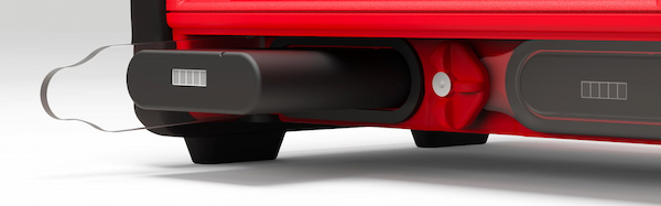
Para abrir un compartimento de batería, gira la perilla de bloqueo central para alinear el borde recortado con el compartimento que deseas abrir.
Las baterías sólo pueden instalarse en la orientación correcta, con la ranura hacia arriba para alinearse con la muesca en la abertura del compartimento.
Te recomendamos cargar completamente tu sistema Ubidium utilizando el cable de carga de CA proporcionado, que se enchufa en el puerto de carga de CA debajo de la solapa del puerto. El estado de carga de las baterías instaladas se mostrará en la pantalla, incluso si el sistema está apagado.
Para encender el sistema, presiona y mantén presionado firmemente el botón de encendido en el teclado principal hasta que el LED de estado se ilumine en verde.
Configuración de la hora
Ubidium contiene un reloj en tiempo real altamente preciso que mantiene la hora precisa incluso cuando el sistema está apagado.
Al iniciar Ubidium, buscará automáticamente una señal de satélite GPS para sincronizar el reloj con la hora del GPS, lo que proporciona la sincronización más precisa disponible.
Debes asegurarte de que la zona horaria esté configurada correctamente en el sistema para tener la hora local correcta. Esto se hace a través del menú de tiempo al que se accede presionando el primer botón de navegación (arriba) en el lado derecho de la pantalla.
Para cambiar la zona horaria, selecciona el elemento de menú que corresponde a "Zona horaria" utilizando las teclas de navegación en el lado derecho de la pantalla.
Desplázate hacia arriba y abajo en este menú utilizando las teclas de flecha para encontrar la hora correcta para tu ubicación y presiona el botón "OK" para guardarla.
Presionar el botón "Atrás" saldrá de cualquier menú abierto y te llevará de vuelta a la pantalla principal de tiempo.
Conectar a la nube
Si planeas utilizar Ubidium como un dispositivo en línea para conectarte a RACE RESULT 12, deberás configurar algunos ajustes básicos para conectar el sistema a tu cuenta.
Desde la pantalla principal de tiempo, abre el menú de red presionando el tercer botón de navegación en el lado derecho de la pantalla.
Dependiendo de cómo te conectarás a Internet, es posible que debas configurar los ajustes de Ethernet, WiFi o Móvil para establecer una conexión a Internet. Para obtener más información, consulta Ubidium Network Settings.
Si estás utilizando una tarjeta SIM de RACE RESULT, simplemente insértala en el puerto SIM que se encuentra debajo de la solapa, y el sistema la configurará automáticamente para ti.
Una vez en línea, selecciona el elemento de menú "Nube" y desde allí deberás configurar el "Número de Cliente" con tu ID de Cliente de RACE RESULT. Para cambiar el número, usa las teclas de flecha arriba y abajo para cambiar cada dígito, y las teclas de flecha derecha e izquierda para seleccionar el dígito. Asegúrate de que si tu ID de Cliente tiene menos de 6 dígitos, el primer dígito debe configurarse en 0. Presiona "OK" cuando hayas terminado para guardar el valor.
Una vez configurado el "Número de Cliente," selecciona "Habilitado" y cambia el valor a "SÍ." También puedes configurarlo para que se active automáticamente al iniciar, si así lo prefieres.
Iniciar el cronometraje
Para empezar a cronometrar con Ubidium, simplemente debes conectar tu Bucle de Cronometraje Activo o Antena de Suelo Plegable de Ubidium al sistema.
Ambos se conectan a los puertos correspondientes en la parte trasera del sistema, protegidos por una tapa de goma. Ten en cuenta que los conectores tipo banana en el compartimento principal del puerto se utilizan para dispositivos de impulso y no se pueden usar para conectar un Bucle de Cronometraje Activo.
Cuando estés operando como un sistema activo, asegúrate también de abrir la Antena de Cronometraje de 2.4 GHz desde su ranura y gírala para que apunte verticalmente hacia arriba.