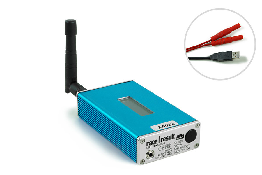
The RACE RESULT USB Timing Box allows you to replace the Decoder and Active Extension with a single USB connection to your PC.
The USB Timing Box can be used time sporting events, scan tags at race pack pickup, or for just about any other application: the open-source software of the USB Timing Box allows you to develop any solution that may have nothing to do with sports timing.
The USB Timing Box is compatible with our Loop Box where the USB Timing Box can receive passings from a Loop Box in Repeat Mode. The USB Timing Box does not include additional functionality such as a 3G connection or GPS time synchronization.
Turning USB Timing Box on/off
To turn the box on, press and hold the button until the center red LED turns off and a boot screen is displayed with information about the system.
To turn off, press the button once. The screen will display the following:
| press again: OFF |
| hold for config |
Press the button again to turn off.
The box will also turn on automatically when connected to via USB and cannot be switched off.
When disconnecting the USB, the device will automatically shut down if there is no loop connected and no passings have been recorded on the device since it was started.
USB Timing Box Configuration
The USB Timing Box has the same settings as the Active Extension: Loop Power, Channel ID, Loop ID. Additionally, the Mode can be set.
The box can be configured by pressing the button for 2 seconds. The first of the four settings will start blinking and can be changed by pressing the button again. By pressing the button again for 2 seconds, the setting will be confirmed and the next setting can be changed. To exit navigating menus, continue holding down the button until no setting blinks anymore.
In this example, the Loop ID is being changed:
| Loop█ 1 020% < |
| CH# 8 TIME |
USB Timing Box Modes
Timing
In this mode, the USB Timing Box operates as a primary timing device. Times from transponders are received and can be read out via the USB serial connection.
It can additionally receive passings from Loop Boxes in Repeat Mode or Stored Passings from transponders.
Kiosk
Kiosk is intended for when the USB TIming Box should be used for short range applications such as race pack collection or transponder assignments. In Kiosk mode the 2.4Ghz sensitivty is greatly reduced and it is anticipated that only detections from transpodners within ~30 cm of the device will be received.
Note that the 2.4Ghz antenna must be connected in order to use Kiosk mode, without the antenna then the sensitivity will be too low to receive any detections.
Repeat
In this mode, the USB Timing Box activates the transponder, receives its data and sends (repeats) it to a primary system.
This is an easy way to connect several timing points within an area, e.g. a triathlon finish, transition in and transition out. The maximum distance between repeating / receiving devices can be up to 900m depending on conditions.
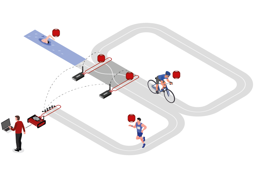
Note that the USB Timing Box has an internal buffer for 1000 detections. Even if the connection between devices is interrupted, the detections will not be lost: once the connection is recovered, the USB Timing Box will transmit the buffered detections. Thanks to the precise internal clock of the device, the detection time will still be correct and precise.
For the communication between devices when using Repeat Mode please note:
- Devices need to run on the same channel (see Channel ID Setup). It is recommended that you select a fixed channel on the main system instead of using the auto mode.
- The main loop that will receive the detections from the devices in Repeat Mode must have Loop ID 1. This way the devices know where to send the data even if several systems are present.
Whilst in Repeat mode USB serial communication is disabled, however the port can still be used for to provide power.
Store & Copy (FW2.5 and above)
This mode only works with the ActivePro and MotorKart transponders, V2 transponders may additionally return less accurate times.
In this mode, when the transponder is activated by the USB Timing Box, it will create a stored passing on the transponder and additionally send a copy of the time to the USB Timimg Box. The passing which is received by the USB Timing box can then be read out via the USB Serial connection as normal.
Additionally note that the copied passing may have lower accuracy than the stored passing or regular Timing Mode, as the internal calculation and communication prioritises the stored passing.
Display Explained
The display of the USB Timing Box can have the following indications:
|
USB Timing Box when it is in Timing mode and connected via USB to a computer. The moving icon in the top right corner indicates that a Loop is connected. The bottom right section of the screen will flash between these two screens. The top screen shows the battery indicator. The bottom screen shows the USB voltage. A range between 5.0V and 4.5V is good. |
||||
|
USB Timing Box when it is in Timing Mode and on battery power. The "19h" displayed in the bottom right corner indicates the time until zero battery in hours. |
||||
|
USB Timing Box when it is in Store&Copy mode and connected via USB to a computer. Store&Copy mode is indicated by an S in the display. |
||||
|
USB Timing Box when it is in Kiosk Mode and connected via USB to a computer. The number "0001" indicates the number of tags scanned since it has been turned on. "ALYFR84" indicates the last transponder seen by the USB Timing Box. |
USB Connection
The USB Timing Box easily connects with the Transponder Module and Timing Module. Your PC should have the appropriate USB drivers to connect to the USB Timing Box. If this not be the case, please see Troubleshooting for instructions on installing Windows drivers.
Ensure that the TagReaderKeyboard and TagTool software are not open when the Transponder Module is connecting with the USB Timing Box. As they use virtual COM ports to connect to the USB Timing Box, it cannot connect to two applications at the same time.
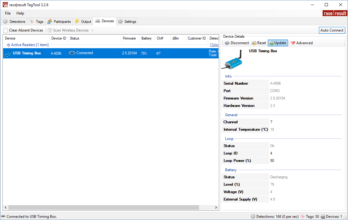
Online Firmware Update
It is recommended to update the firmware when a new firmware is available. See Firmware Release Notes.
For firmware updates for the USB Timing Box and USB Management Box open your TagTool and connect your device, the most recent Active Device firmware is included in the most recent release of TagTool. Once it is connected, select the device you wish to update then click Update in the Device Details window, and select the most recent firmware version (highest value name). It is important that you do not unplug the device during the update.