
El decodificador de RACE RESULT recibe las señales de los transpondedores utilizando antenas, luego calcula y guarda el tiempo final de detección, basándose en un reloj súmamente preciso y la intensidad de la señal de los transpondedores al cruzar la línea de cronometraje.
Proporciona estos datos (número de dorsal, tiempos e información adicional) al software de puntuación, como RACE RESULT 12 o carga los datos directamente a un servidor de Internet.
El decodificador no realiza cálculos adicionales, como el cálculo del tiempo neto, los tiempos de vuelta, etc. Todo esto lo hará su software de puntuación.
También le garantiza un funcionamiento sin interrupción, ya que funciona independientemente de una computadora y una fuente de enrgía externa. Toda la información se almacena automáticamente en el dispositivo.
Seguridad y Regulaciones
Responsabilidades Generales de Seguridad
Esta unidad ha sido diseñada y probada de acuerdo al Certificado de Conformidad CE y ha comprobado que la fábrica cumple complétamente con las normas de seguridad.
Para mantener esta condición y garantizar un funcionamiento seguro, el usuario debe leer todas las instrucciones y advertencias que se incluyen en este manual de operación.
En todos los trabajos realizados deben observarse las normas de seguridad locales y nacionales aplicables y las normas para la prevención de accidentes.
Declaración FCC/IC
Los cambios o modificaciones no aprobados claramente por los responsables del cumplimiento podrían anular la autoridad del usuario para operar el equipo.
Este equipo cumple con la Parte 15 de las Reglas FCC y con la Licencia-Exenta RSS de la Industria de Canadá. El funcionamiento está sujeto a las siguientes dos condiciones: (1) este dispositivo no puede causar interferencias perjudiciales y (2) este dispositivo debe aceptar cualquier interferencia recibida, incluidas las interferencias que puedan causar un funcionamiento no deseado.
Advertencias y Precauciones
Las siguientes alertas son usadas en este manual:
- ADVERTENCIAS alertan a los usuarios de situaciones potencialmente peligrosas.
- PRECAUCIONES alertan a los usuarios de posibles daños al equipo.
Las Advertencias y Precauciones están indicadas por:
- El texto ADVERTENCIA o PRECAUCIÓN
- Una descripción explicando el peligro y cómo evitarlo
- El Ícono:

Dónde Operar el Sistema
UHF opera a nivel mundial en diferentes frecuencias (por ejemplo, Europa 865 - 868 MHz, EE.UU. 902-968 MHz, AUS 920-925 MHz) con diferentes requisitos regulatorios. Es por eso que RACE RESULT proporciona diferentes versiones del sistema para diferentes áreas regulatorias. Al operar la parte pasiva del sistema en otro país, asegúrese de que cumpla con la normativa local.
El Sistema Activo RACE RESULT usa frecuencias universales que pueden usarse globalmente.
Elementos del Decodificador
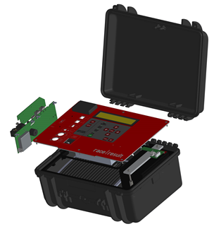
Estuche
La electrónica del decodificador de RACE RESULT está integrada en un estuche rígido y sólido. Debido a los conectores en el panel frontal, el panel frontal no es impermeable. Por lo tanto, tenga en cuenta:
 Durante lluvia, la tapa del decodificador debe estar cerrada y bloqueada. Por lo tanto, todos los cables deben pasar a través de la ranura entre el panel frontal y la tapa en el lateral.
Cuando opere el sistema a temperaturas altas (> 25 ° C / 80 ° F) y esté ubicado bajo la luz directa del sol, la tapa debe abrirse. De lo contrario, el sistema puede hacer un apagado de emergencia activada por la temperatura.
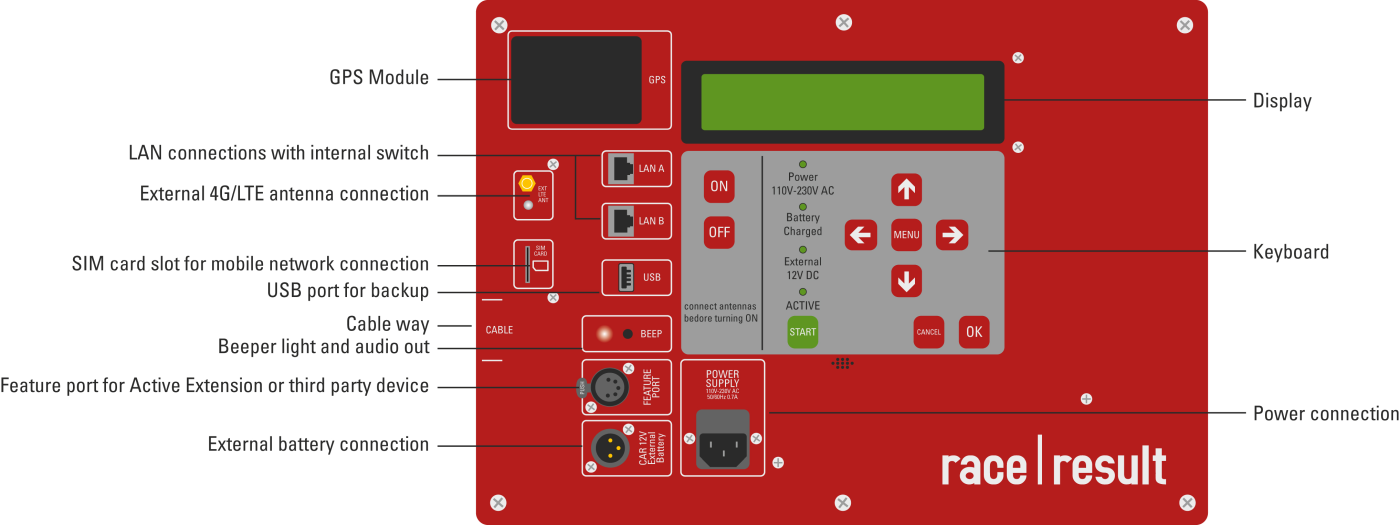
Conectores
El estuche del decodificador tiene los siguientes conectores en el panel frontal:
|
Corriente |
Fuente de alimentación, 110-240V AC, 50/60Hz. |
|
Batería Externa |
Usando el cable incluido, el decodificador se puede conectar a una batería externa o al encendedor de un automóvil (vea Puerto de Batería Externa). |
|
Ethernet |
Las detecciones pueden ser leídas a través de una conexión de red (vea Conexión Ethernet). |
|
USB |
Usando el puerto USB, las detecciones pueden guardarse en una memoria USB (vea Conexión USB). |
|
Audio |
El decodificador contiene un bíper interno, el cual emitirá una señal acústica en cada detección. Alternativamente, puede conectar un altavoz externo o auriculares. La señal acústica interna se apagará. |
|
Puerto Funcional |
El puerto funcional sirve para conectar accesorios adicionales, incluido el Active Loop (vea Puertos Adicionales). |
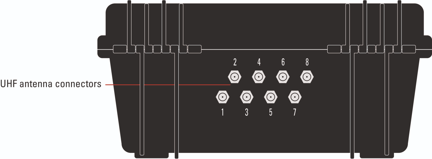
Adicionalmente, el estuche del decodificador cuenta con 8 conectores de antena para la antena UHF pasiva en la parte trasera (vea Configuración de la Antena Pasiva para más detalles sobre la configuración).
Pantalla Principal y Teclado
La pantalla tiene una luz de fondo integrada y es fácil de leer tanto en la oscuridad como a la luz del día.
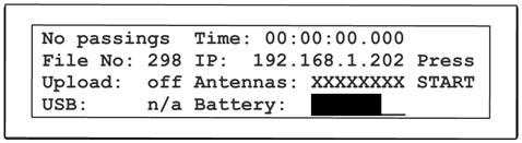

La pantalla muestra la siguiente información:
| Columna Izquierda | |
|
Cuenta/Count |
mustra el número de detecciones desde el último Inicio, o No Passings. |
|
Num. del Archivo/File No |
muestra el número del archivo de los pases actuales, vea Modo de Prueba y Modo de Cronometraje |
|
Carga/Upload |
muestra el estado del servidor de carga, vea Carag 2G/3G |
|
USB |
muestar el estado de la memoria USB, vea Puerto USB |
| Columna Media | |
|
Tiempo/Time |
muestra un tiempo de ejecución (puede ser la hora del día o el tiempo de la carrera, vea Configuración de Tiempo) |
|
IP |
muestra la dirección IP del sistema, vea Conexión Ethernet |
|
Antenas/Antennas |
muestra el estado de las 8 antenas pasivas, o detalles de la Extensión Activa (Active Extension) |
|
Batería/Battery |
muestra el estado de la batería interna, vea Batería |
|
Columna Derecha |
muestra el ID de los últimos 4 transpondedores detectados (o presione START cuando aún esté en Modo de Prueba/Test Mode, vea Modo de Prueba y Modo de Cronometraje) |
Batería
El decodificador cuenta con una batería interna de plomo-ácido con capacidad de 15Ah, la cual dura entre 6 y 8 horas con la antena pasiva o 24 horas con el active loop.
Puede cargarse mientras se ejecuta, por lo que se recomienda conectar el decodificador a un suministro externo durante la carrera, si hay alguno disponible.
Cargar una batería vacía toma aprox. 4 horas cuando el decodificador está apagado, y 8 horas cuando se está ejecutando. El LED Battery Charged/Batería cargada en el teclado indica que la batería se ha cargado al menos en un 75%.
La batería cumple con las disposiciones especiales A48 y A67 de la IATA. Por lo tanto, el sistema puede manejarse como carga común tanto para envíos aéreos como para barcos.
Conexión de Datos
Los datos de cronometraje ("detecciones" o "pases") se pueden recuperar de cuatro maneras diferentes:
- via la interfaz Ethernet
- via el puerto USB
- Al cargar los datos a través del módulo interno 2G/3G/4G, los datos pueden descargarse de Internet
- Accediendo al decodificador a través de su navegador
Conexión de Red/Ethernet
Ethernet/Conección de Red
La conexión Ethernet es el tipo de conexión recomendado para leer en vivo los datos del sistema durante la carrera. El sistema se puede conectar directamente a una computadora mediante un cable de conexión estándar o cruzado, o puede integrarse en una red local mediante un conmutador o enrutador.
El Sistema RACE RESULT ofrece dos puertos Ethernet y ambos puertos pueden usarse para conectarse a una computadora/conmutador. El puerto adicional se puede utilizar, por ejemplo, para conectarse a otro sistema RACE RESULT (paso). Tanto los puertos Ethernet como el propio sistema RACE RESULT están conectados a través de un conmutador interno.
Los parámetros de la conexión Ethernet se pueden definir en el menú Red.
De forma predeterminada, está configurado en DHCP para que el sistema recupere una dirección IP dinámica de un enrutador/servidor DHCP en su red. Para el cronometraje de carreras, puede ser mejor asignar direcciones IP fijas a cada sistema. Para eso, simplemente desactive DHCP e ingrese la dirección IP manualmente (también puede configurar la máscara de subred, la puerta de enlace estándar y el servidor DNS que serán necesarios cuando el decodificador necesite acceder a Internet, por ejemplo, para una actualización de firmware).
Para más información sobre la configuración de red vea Networking Guide
Puerto USB
El puerto USB sirve para guardar los archivos de detección en una memoria USB. Esto se puede hacer después de la carrera o en vivo durante la carrera. Al conectar una memoria USB, el decodificador mostrará un mensaje que indica que se detectó una memoria y copiará todos los archivos de transferencia existentes a la memoria. Se creará una carpeta separada con el nombre del ID del decodificador.
Si se enchufa una memoria USB durante la carrera, el sistema guardará las nuevas detecciones cada pocos segundos en la memoria. Esto puede servir como una copia de seguridad adicional: en teoría, incluso si el decodificador se descompusiese, los datos que pasan se almacenan en la memoria USB, que puede ser extraída.
 No retire la memoria mientras el sistema está en modo de cronometraje. Esto puede destruir el sistema de archivos en ella.
Para el formato de datos de los archivos pasando, consulte Formato de Archivo de Datos.
Mobile Upload
The integrated 4G module (previously 2G or 3G) can be used to upload the detection data to a RACE RESULT database in the Internet. The data can then be downloaded from any place with an Internet connection. In other words, this is an easy way to connect remote timing points.
Upload
To upload the detections using the 4G/LTE module proceed as follows:
- Insert your SIM card in the SIM card slot.
- Go to the menu Upload.
- Enter your RACE RESULT customer number and the PIN of your SIM card
- Leave the mobile APN config setting on "auto". Your provider settings will probably be automatically recognized by the decoder. If not, select "manual" and read the sub-section of this article below to find out how to set up your APN.
- Set the option Enabled to yes.
The modem will go through successive connection stages detailed below as well. Once upload is successfully activated, the upload count on the display should match the current detection count.
You can also upload the data via an Ethernet connection with Internet connectivity. If the the decoder has access to the Internet via one of its Ethernet ports, the IP information on the display is marked with an asterisk. The upload feature automatically uses Ethernet when available, and falls back to 4G if the connection via Ethernet is lost.
Mobile Usage
In the second page of the Upload settings you can set the preference for usage of mobile upload.
There are 3 options for mobile upload.
- Fallback - The mobile GSM will only connect if upload is enabled and no internet connection is available via either the ethernet or via USB Wi-Fi adapter. If the connection drops from a preferred source then the module will attempt connection.
- Hot-Standby - The mobile GSM will connect always even if an alternative internet connection is available. If the connection drops from a preferred source the system will immediately switch to this.
- Preferred - The mobile GSM upload will be used at all times regardless of internet connection via either ethernet or USB Wi-Fi adapter.
Upload Target
In the second page of the Upload settings you can also set the upload target for the data.
As of firmware version 2.58, there are 2 options for upload when working with RACE RESULT 12.
- race result - This uploads via TCP protocols for communication with the Timing Module. This also includes an HTTP fallback in the event that the TCP connection is unstable which will also provide data to the Timing Module.
- race result (obselete) - This uploads data to our HTTP server, this will be fully deprecated at the end of 2021 and should not be used.
Download
When using RACE RESULT 12, you can download the passing data in the Timing Module.
To download the data using your own software, please consult Online Storage Communication Protocol.
Browser Access
You can easily access the decoder by entering the IP address in your browser, e.g. http://192.168.1.43
In the browser you can:
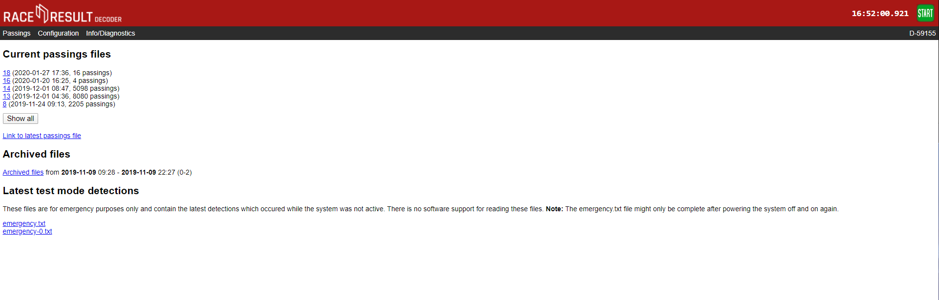
- Access all (old) passing files. Note that you cannot delete passing files. When the internal memory of 85 MB is full (it can save over 1 million detections), the oldest files will be deleted automatically.
- Access emergency data files. These are created during test mode and are stored automatically when timing is stopped.
- Set the time zone
- Configure upload settings including Custom APN Configuration, upload target and client mode.
- Upload Diagnostics Data
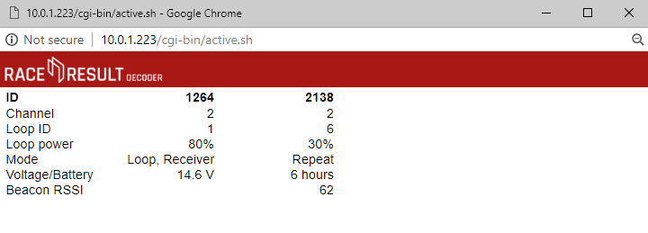
- Check the status of connected Loop Boxes
- Start / Stop Timing mode
Show Active Systems
When connected to an active extension there is an option to view active systems, this allows you to see the status of the active extension and any connected loop boxes. This will open in a new mini window.
Passings
All passings files on the decoder can be accessed through the browser interface, any non-archived files will be shown immediately, when files are archived they are grouped together by the date range and can be downloaded.
There are 2 emergency files which are also available, these store the last detections from when the decoder was in test mode. emergency.txt is the most recent and emergency-0.txt is older passings.
There is no support to read this directly in to RACE RESULT 12 and so these files should not be relied on for timing.
Configuration
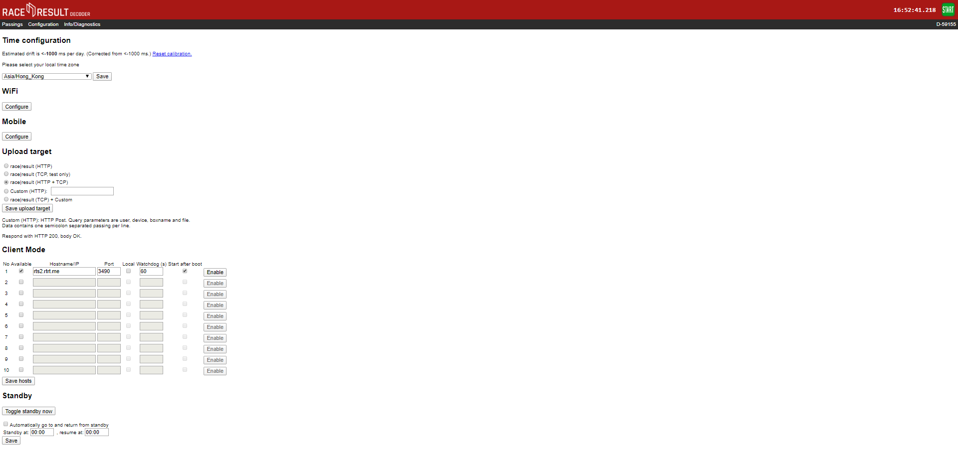
The configuration tab allows for some additional configuration of settings which cannot be achieved through the decoder menu.
Time Drift
Here you can view the estimated time drift, this is the variation in time that may occur on the decoder, leaving the decoder turned on connected to the internet via ethernet can help to reduce this time drift, resetting the calibration will force the decoder to recalculate the time drift.
Time Zone
The time zone of the decoder can also be changed here using the drop down.
2G/3G
If you need to use custom APN settings for your Sim cards then these will need to be configured through the browser interface. You can also find your Decoders IMEI number from the Mobile Configuration page.
Upload Target
Decoders support upload to both HTTP and TCP, you can choose which method to use or define a custom HTTP target. HTTP upload is used for the Transponder module and Connector software, TCP upload is used for the new Timing Module. We advise using both HTTP and TCP for backup whilst the Timing Module is still undergoing development work.
Client Mode
You can use the decoder as a TCP server to pull data to a client, this is used by some third-party tracking platforms and timing software. There are a maximum of 10 TCP clients which can be configured with the IP address, port number, watchdog and auto-enable.
Find out more in our Developers Section
Standby
Standby is used in some permanent installations where the decoder can be powered down over night to preserve battery, it is not advised to set this for normal events as it could cause premature shut down.
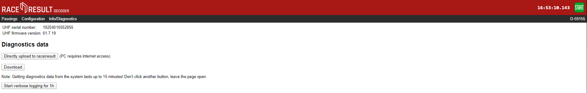
Info / Diagnostics
The info tab shows the UHF reader serial number and firmware version, and also allows you to upload the decoders diagnostics file directly to race result or download it to send to us. This may be required if you experience abnormal behaviour with your decoder during it's use.
Formato de Archivo de Datos
Los pases en los archivos de pases están almacenados en el siguiente formato:
<PassingNo>;<Bib/TranspCode>;<Date>;<Time>;[<EventID>];<Hits>;<MaxRSSI>;
<InternalData>;<IsActive>;[<Channel>];[<LoopID>];[<LoopOnly>];[<WakeupCounter>];
[<Battery>];[<Temperature>];[<InternalActiveData>];BoxName<CrLf>
|
<PassingNo> |
Número de registro de pases, comenzando en 1 para el primer pase. | ||||||||||||||||
|
<Bib/TranspCode> |
Número de dorsal del transpondedor (o código del transpondedoren caso de tags multi usos o transpondedores activos) |
||||||||||||||||
|
<Date> |
Formato: aaa-MM-dd Si se usa GPS, fecha de la detección, de otra manera 0000-00-00 o 000-00-01 después de 24 horas y así en adelante. |
||||||||||||||||
|
<Time> |
Tiempo de la detección, formato: hh:mm:ss.kkk |
||||||||||||||||
|
<EventID> |
ID del conjunto de dorsales. La combinación de <Bib> y <EventID> es única para todos los transpondedores de dorsales producidos de RACE RESULT. En caso de tags multi uso <EventID> es 0 o vacío. |
||||||||||||||||
|
<Hits> |
Número de veces que el tag fue detectado. |
||||||||||||||||
|
<MaxRSSI> |
Máximo valor RSSI encontrado mientras se determina <Time>. |
||||||||||||||||
|
[<InternalData>] |
Este campo solo es usado para propósitos internos y es opcional. |
||||||||||||||||
|
<IsActive> |
1, si este pase es de transpondedor activos. |
||||||||||||||||
|
[<Channel>] |
Canal ID (1 -> 8) |
||||||||||||||||
|
[<LoopID>] |
Loop ID (1 -> 8) |
||||||||||||||||
|
[<LoopOnly>] |
1, si esta detección fue generada en modo de almacenamiento. |
||||||||||||||||
|
[<WakeupCounter>] |
Contador general de reactivación del transpondedor (transpondedores nuevos empiezan en 10000). |
||||||||||||||||
|
[<Battery>] |
Nivel de batería en voltios. |
||||||||||||||||
|
[<Temperature>] |
Temperatura en grados Celsius. |
||||||||||||||||
|
[<InternalActiveData>] |
Detalles de transmisión de datos. Un byte. Los tres bits más bajos: contador de canal ocupado (número de veces, que el pase no se pudo transmitir porque el transpondedor no pudo acceder al canal). Siguientes tres bits: Sin contador ACK (número de veces que el pase se transmitió, pero no se reconoció). Séptimo bit: 1, si este pase no se pudo transmitir en un intento anterior (="pase almacenado", pase antiguo), de lo contrario 0. Bit más alto: 1, si el transpondedor despertó de sueño profundo debido al pase, de lo contrario 0. Consejo: Puede checar si el pase es un pase almacenado usando Hint: You can check if a passing is a stored passing using [InternalData] & 0x40 == 0x40
|
||||||||||||||||
|
[<BoxName>] |
Nombre del decodificador. Por defecto el ID del dispositivo. |
||||||||||||||||
Modo Cliente
El Modo Cliente se utiliza para las conexiones salientes a software / plataformas de terceros, se configura a través del decodificador Acceso al navegador, el modo cliente se puede utilizar para conectarse a servidores TCP/IP locales o a servidores en línea. Los usos más comunes incluyen plataformas de seguimiento de terceros y la integración de software de fotofinish.
Cuando el Modo Cliente está habilitado el decodificador intentará hacer una conexión con el servidor especificado, una vez conectado permite que el servidor envíe comandos al decodificador para extraer datos y también cambiar la configuración.
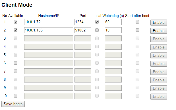
Para configurar el Modo Cliente, necesitará el nombre del servidor, la dirección URL o la dirección de puerto; si el servidor está en la red local, marque la opción local. El watchdog es la frecuencia con la que el decodificador espera comandos del servidor, de lo contrario intentará reconectarse.
Cuando el Modo Cliente está habilitado, los contadores de carga en la pantalla se alternarán entre los recuentos de carga normales (Carga / HTTP Up) y TCP Out. TCP Out mostrará el número de conexiones que están activas a través del Modo Cliente, si muestra 1 o más entonces está conectado al servidor(es).
Modo de Prueba y Modo de Cronometraje
Después del arranque, el decodificador está en Modo de Prueba, es decir, no almacena ninguna detección. En su lugar, suena constantemente un pitido/parpadea cuando ve un transpondedor. De esta manera:
- La configuración del sistema se puede verificar fácilmente para asegurarse de que se detecte como se espera.
- No es necesario filtrar ninguna detección en el software de puntuación del calentamiento de los atletas antes de la carrera.
Modo de Cronometraje
El Modo de Cronometraje se iniciará al presionar el botón de START en el teclado. Si no se ejecuta en tiempo GPS, el tiempo comenzará a partir de las 0:00:00 y el decodificador comenzará a procesar y registrar de inmediato todas los tags que pasan por la antena.
Detener el Modo de Cronometraje
El Modo de Cronometraje se puede detener presionando el botón CANCEL o seleccionando la opción Stop Timing en el menú. El sistema estará de nuevo en Modo de Prueba.
La siguiente ocasión que se inicie el Modo de Prueba, el sistema crea un nuevo archivo para las detecciones, indicado por un nuevo número de archivo en la pantalla principal. Nótese que:
- A través de la interfaz de Ethernet, solo las detecciones de los archivos actuales se pueden leer.
- Se puede acceder a todos los archivos (antiguos) a través del browser o una memoria USB (vea Conexión de Datos).
Archivo de Emergencia
Si olvida iniciar el Modo de Cronometraje, todavía puede acceder a un archivo de pases de emergencia a través de Acceso con Navegador.
Ajustes de Tiempo
Cuando se encuentre en Modo de Prueba, el tiempo del decodificador puede ser ajustado a través del menú Time. Las siguientes opciones están disponibles:
Establecer Tiempo de Ejecución
El tiempo ingresado será ajustado y empezará a correr incluso estando en Modo de Prueba. Esta opción se usa normalmente para ajustar la hora del reloj/hora del día.
Ajustar el Tiempo de Inicio
La hora ingresada se configurará, pero no comenzará a funcionar antes de iniciar el Modo de Cronometraje. Esta opción se usa generalmente para ajustar la hora a 0:00:00.
Ajustar Tiempo de GPS
Al usar esta opción, el sistema intentará recibir la hora precisa de un satélite GPS. Puede ser que la señal de GPS no se pueda recibir dentro de los edificios y debajo de los árboles. En este caso, el sistema mostrará un mensaje de error después de 60 segundos.
Configurar la hora del GPS
Dentro de la configuración puede establecer la zona horaria que el decodificador debe utilizar y ajustar el valor de los Segundos Bisiestos (normalmente sólo se requiere cuando se trabaja con hardware de terceros que no corrige los segundos bisiestos).
Ajustes de Detección
Tiempo de Reacción
Cuando un chip se acerca a la antena de tierra, el sistema de RACE RESULT monitorea la intensidad de la señal del chip. Una vez que pasa sobre la antena, el sistema registra el tiempo de mayor intensidad de señal, que se espera que esté directamente sobre la antena. El Tiempo de Reacción (Reaction Time) en el menú Detección (Detection) define cuánto tiempo más se controlará un chip después del último pico de intensidad de señal antes de proporcionar el tiempo final.
Al aumentar el tiempo de reacción, los tiempos de finalización calculados serán más precisos, pero tomará más tiempo hasta que el sistema pueda proporcionar este tiempo. Cuando se usa un tiempo de reacción pequeño, el sistema puede identificar la detección muy rápidamente, pero la precisión se reducirá.
El valor predetermindado es de 850 ms. Si es necesario, este valor se puede disminuir para carreras rápidas (por ejemplo, de bicicleta de montaña) y aumentar para carreras lentas (por ejemplo, de niños). Para una precisión óptima, el valor del tiempo de reacción debe coincidir con el tiempo promedio que el chip estará en el rango de las antenas.
Tenga en cuenta que el ajuste del tiempo de reacción en el decodificador solo aplica para el sistema pasivo. Para el sistema activo, el cálculo del tiempo ocurre en el nivel de transpondedor.
Tiempo Muerto
El Tiempo Muerto / Dead Time en el menú Detección / Detection define el tiempo mínimo entre dos lecturas del mismo chip.
En el modo de legado pasivo Detección cada dt ms y al usar el sistema activo, el decodificador simplemente ignora las lecturas adicionales del mismo chip durante el tiempo muerto, después de que se haya almacenado una primera lectura.
En los modos First detection only (Solo la primera detección), Last detection only (Solo la última detección) , Firts + last detection (Primera + última detección) que se introdujeron en las versiones más recientes del firmware, el decodificador verifica si el chip está todavía en el rango durante el tiempo muerto después de que se haya almacenado una primera lectura.
El valor predeterminado del tiempo muerto es de 5000ms. Puede ser ajustado a valores entre 0 y 9999ms.
Modo de Detección
El Sistema RACE RESULT soporta cuatro diferentes modos de detección pasiva:
- First+last detection (predeterminado): el decodificador almacena una primera detección basada en el valor del tiempo de reacción. Si el chip permanece en el campo después de esta primera detección, el decodificador esperará a que el chip abandone el campo por un tiempo mayor que el tiempo muerto, y además informará la última detección antes de que el chip haya salido del campo.
- First detection only: el decodificador almacena una primera detección basada en el valor del tiempo de reacción. Solo almacena una nueva detección para el mismo chip después de que el chip haya estado fuera del campo de detección por un tiempo mayor que el tiempo muerto.
- Last detection only: cuando el chip entra en el campo de detección, el decodificador lo busca durante el tiempo muerto. Cuando no ve el chip por un tiempo mayor que el tiempo muerto, almacena la última detección antes de que el chip salga del campo de detección.
- Detection every dt ms: el decodificador almacena una primera lectura basada en el valor del tiempo de reacción, luego simplemente ignora cualquier lectura adicional del mismo chip durante el tiempo muerto.
El modo First+last detection es el predeterminado, ya que es el que le brinda la información más completa en cualquier situación (un inicio, una división o un final) y le permite elegir la lectura correcta a nivel de software. First detection only y Last detection only están diseñados para casos especiales y deben utilizarse con extremo cuidado, por ejemplo, solo use el primero de ellos para una finalización o una ubicación de tiempo dividida, y el último en un escenario de inicio.
Inicialmente, solo estaba disponible el modo Detection every dt ms. Ahora recomendamos no usarlo más, especialmente en un escenario de inicio. Si un participante permanece en la línea durante mucho tiempo antes del inicio, normalmente recibirá muchas detecciones (una cada 5 segundos), y solo necesita la última. Al usar este modo, la última detección es imprecisa, y si el corredor se detecta justo antes de que la pistola dispare y deje el campo de detección antes de que transcurra el tiempo muerto, no tendrá una detección de inicio válida después de T0. Los nuevos modos surgieron precisamente para abordar estos problemas.
Pitidos / Parpadeos
La configuración On Detection/En Detección en el menú Detection/Detección define si el decodificador debe pitar y/o parpadear para signalizar una detección.
Tenga en cuenta que hay un límite para la frecuencia de los pitidos y parpadeos, estos solo se ponen en cola durante 2 segundos. Si se detectan demasiados atletas al mismo tiempo, el sistema no podrá emitir pitidos ni parpadear por cada atleta, y usted no podrá distinguir cada señal por separado.
Si la densidad de los atletas cruzando el sistema de cronometraje es baja, el sistema emitirá una señal de cada detección por separado con un breve retraso para que pueda verificar el número de detecciones fácilmente .
Active Extension Settings
| Channel: 7 |
| Power: 040% |......█.............| |
| Loop ID: 1 (Base) |
| Discard stored detections: NO |
Canal ("Channel")
Para la extensión activa, la identificación del canal está configurada en automático de forma predeterminada. En este caso, el sistema realiza un sondeo de canales cuando se enciende y selecciona el canal menos utilizado para evitar interferencias entre el sistema activo y otros dispositivos. Tenga en cuenta que:
- Incluso si Wi-Fi utiliza mucho un canal, todavía habría suficientes espacios para operar el sistema activo en el mismo canal.
- El modo automático generalmente seleccionará el canal 1 porque Wi-Fi no usa este canal y, a menudo, es completamente gratuito.
Si es necesario, se puede seleccionar un canal diferente, al seleccionar la configuración del canal, el sistema primero realizará una búsqueda de canales y luego mostrará los canales y sus cualidades. Debe seleccionar los canales con el porcentaje más alto, este es el canal más claro y tendrá la menor interferencia.
| Channels (Quality) |
| Always select channel automatically |
| 1( 32%) 2( 36%) 3( 0%) 4( 0%) |
| 5( 50%) 6( 10%) ►7( 65%)◄ 8( 61%) |
Potencia ("Power")
Ajuste la potencia del bucle ("loop") con las teclas de flecha izquierda y derecha. Para comprender cómo afecta la potencia del lazo al rendimiento véase Loop Power.
Tenga en cuenta que la "Active Extension" determina automáticamente la longitud del bucle y adapta la potencia real en el bucle en consecuencia, de modo que el mismo valor porcentual siempre debería dar como resultado aproximadamente la misma altura de lectura.
Loop ID
Al igual que el canal, Loop ID normalmente se ejecuta en modo automático. La extensión activa RACE RESULT, la caja de sincronización USB ("USB Timing Box") y la caja de bucle ("Loop box") envían una baliza de estado cada segundo en su canal de repetición. Al encender una extensión activa con modo de bucle automático, escuchará durante unos segundos las señales de los otros dispositivos activos y luego seleccionará una ID de bucle no utilizada.
El modo de bucle automático es fácil de usar, pero puede ser más fácil asignar ID de bucle fijos para que sepa inmediatamente qué ID de bucle pertenece a qué dispositivo. Asegúrese de no asignar una ID de bucle dos veces; de lo contrario, recibirá las detecciones en ambos dispositivos activos (cuando se ejecutan en el mismo canal).
Si selecciona accidentalmente una ID de bucle que ya se está utilizando, la ID de bucle parpadeará entre la ID de bucle ocupada y una X. El siguiente ejemplo muestra un sistema RACE RESULT con una ID de bucle que ya se ha seleccionado. A otro dispositivo activo se le ha asignado este ID de bucle, por lo que no debe usarse.
| C | o | u | n | t | : | 3 | 8 | 2 | 3 | T | i | m | e | : | 1 | 1 | : | 4 | 0 | : | 2 | 3 | . | 3 | 2 | 3 | z | z | z | z | z | 0 | 1 | ||||||
| F | i | l | e | N | o | : | 2 | 9 | 8 | I | P | : | 1 | 9 | 2 | . | 1 | 6 | 8 | . | 1 | . | 2 | 0 | 2 | z | z | z | z | z | 0 | 1 | |||||||
| U | p | l | o | a | d | : | o | f | f | C | h | # | : | 1 | L | o | o | p | # | : | X | 5 | 0 | % | z | z | z | z | z | 0 | 1 | ||||||||
| U | S | B | : | n | / | a | B | a | t | t | e | r | y | : | █ | █ | █ | █ | █ | █ | █ | █ | z | z | z | z | z | 0 | 1 |
V1 Legacy Mode
De manera predeterminada, el modo heredado de V1 está configurado en AUTO, en este modo utilizará los canales principal y de respaldo para recibir datos de paso; sin embargo, si se detecta un transpondedor que no admite esto, la conmutación se desactivará hasta que se reinicie el sistema; o la configuración sea modificada manualmente.
El cambio de canal se puede establecer en "ENCENDIDO" para mantenerlo siempre encendido, o en "APAGADO" para deshabilitarlo siempre, sin embargo, esto no se recomienda ya que olvidar volver a cambiar la configuración podría tener un impacto negativo en la transmisión de datos.
Active Transponder Processing
The Active Transponder Processing determines how quickly Active passings will be processed and stored, there are three available modes.
- Smart
The system compares the Channel and Loop IDs of the passing to the current settings of the Active Extension. If the system receives passings with different IDs (e.g. from a Loop Box) it will enter a delayed mode. The system will then wait for 500ms to sort the passings to try and ensure they are stored in the correct order. The delayed mode is disabled again if no transponder is seen with a different Channel and Loop ID.
- As fast as possible
This is especially designed for TV productions. The system will store and forward the passings immediately. If the timing point has a lot of traffic over the 2.4GHz then it is possible that the passings are stored in the wrong order.
- Wait at least
Define a custom timeout for how long the Decoder should wait to sort the passings before storing them.
Puerto Funcional
El puerto funcional sirve para conectar cualquier tipo de accesorios al sistema RACE RESULT. Proporciona tierra, +12V, +5V, RX y TX. Además de la Extensión Activa (vea Ajustes del Loop Activo), existen varios Accessorios que puede conectar.
Las clavijas en el puerto funcional se utilizan de la siguiente manera:
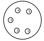
1: +4,8V salida (5V - diodo Shottky) (500mA max)
2: +11V-15V (Sin fusible! 2 Way!)
3: TXD 3,3V TTL
4: RXD 3,3V TTL Pull Up 10k interno
5: IO Disparador digital - max 3,3V
SHIELD = GND
 Use equipo que no sea de RACE RESULT bajo su propio riesgo!
Los cortos circuitos dañarán el sistema.
Solo use conectores originales Neutrik, los conectadores baratos no conectan GND de manera confiable.
Puerto de Batería Externo
La batería interna del sistema de RACE RESULT tiene una duración de aproximadamente 6-8 horas (antena de tierra pasiva), o 24 horas (Active Loop). El puerto de batería externo se puede utilizar para conectar una batería más grande o un automóvil (a través del encendedor de cigarrillos) si no contará con otra fuente de alimentación durante mucho tiemo.
Al determinar el tamaño necesario de una batería, calcule con un consumo de energía de 2A utilizando la antena pasiva y 500mA utilizando el loop activo.
El sistema se vende con un cable especial con conector XLR para el decodificador en un extremo y un conector para automóvil en el otro. Las clavijas se utilizan de la siguiente manera:
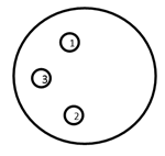
1: GND
2: +12V Entrada (10A Fusible)
3: NC
SHIELD = GND
Tenga en cuenta que la batería externa no carga la batería interna, sino que, en cambio, toma energía de ambas baterías, interna y externa, al mismo tiempo.
Puede usar el Acelerador de Batería para descargar la batería externa primero.
Opciones de Inicio
En el menú System (Sistema), la opción Startup (Inicio) se puede configurar con los siguientes valores:
| do nothing | No hacer nada después de una configuración normal. |
| set GPS time | Configure el tiempo de GPS después de que el decodificador se haya iniciado. |
| GPS time & activate | Configure la hora del GPS y active el modo de operación después de que se haya iniciado el decodificador. |
| GPS time, activate & upload | Configure la hora del GPS, active el modo de operación y cargue (con la configuración actual) después de que se haya iniciado el decodificador. |
| GPS time & upload | Configure la hora del GPS y comience a cargar (con la configuración actual) después de que se haya iniciado el decodificador. |
Marcadores
Al presionar nuevamente el botón START en el Modo de Cronometraje (Timing Mode), se creará un marcador adicional. Un marcador es una detección falsa con un cierto número de dorsal que se puede utilizar en el software de puntuación, por ejemplo, para indicar el inicio de una segunda ola de inicio.
Para habilitar los marcadores, abra la configuración Trigger Impulse desde el Menú. El Modo de Cronometraje debe configurarse en "default (+marker)".
Advertencia: cambiar esto sin la comprensión de los otros modos, resultará en pérdida de datos del cronometraje.
Al cambiar el Marcador se alternará entre "off", el número del marcador que se puede editar y la opción de crear un nuevo archivo en lugar de un marcador. Es bueno asegurarse de que el número del marcador no se superponga con sus rangos de números de dorsales, esto puede establecerse con cualquier valor hasta 999999. También hay una opción para aumentar este número cada vez que se crea un marcador.
Los marcadores también se pueden configurar usando Accesorios para Puerto Adicional o entrada de 3.5 mm de la Extensión Activa o Cajas Loop. Para utilizar la entrada de la Extensión Activa, asegúrese de cambiar la configuración de I/O, en la segunda página del menú de Extensión Activa, a "Trigger In".
Si se utilizan entradas externas, como photocell o puertas de arranque, es posible que desee establecer el ajuste de Arranque Externo en "sí". Con esta opción activada, la sensibilidad del disparo se incrementa para asegurar que se capturen todos los disparos. Cuando se ajusta a "no" el pin de disparo se vuelve a comprobar después de un breve retraso para evitar falsos disparos, pero con eventos rápidos esto podría resultar en disparos perdidos.
En RACE RESULT 12 los marcadores se identifican automáticamente y se listan en el menú Start Times / Finish Time Limits, los marcadores se almacenan internamente con un dorsal de acuerdo con el número de marcador establecido en el decodificador.
Atención: Si un número de marcador coincide con el dorsal de un participante en el archivo del evento, el marcador se asignará al participante.
Modos de sincronización alternativos
Advertencia: Estas configuraciones deben usarse con mucha precaución; ya no se recomiendan al cronometrar/puntuar con RACE RESULT 12, ya que los marcadores se pueden asignar directamente en el software.
De forma predeterminada, el modo de sincronización está configurado en +Marcador, lo que agregará marcadores al archivo de paso con el número de marcador asignado.
Alternativamente, es posible hacer coincidir los marcadores con las lecturas del transpondedor en el decodificador directamente; esto se usa en eventos como MTB cuesta abajo donde el transpondedor se usa para la identificación, pero el tiempo debe tomarse de un marcador de una entrada de disparo, como una fotocélula.
Dependiendo de la configuración, puede asignar al sistema para que busque: primero el chip (1. chip, 2. fotocélula) o el marcador primero (1. fotocélula, 2. chip).
También se puede establecer un tiempo máximo entre chip/celda.
Si no se recibe un marcador de acuerdo con las reglas, entonces el tiempo del transpondedor no se guarda. Por este motivo, este modo no debe utilizarse en circunstancias normales.
Actualización de Firmware En Línea
Hay actualizaciones frecuentes de firmware, por ejemplo, para nuevas funcionalidades o nuevos accesorios. Se recomienda actualizar el firmware con frecuencia. Ver Notas de la versión de Firmware.
Para actualizar el firmware de su decodificador, proceda de la siguiente manera:
- Asegúrese de que el sistema esté conectado a una fuente de alimentación externa para que no se quede sin batería durante el proceso de actualización.
- Conecte un cable Ethernet con conectividad a internet.
- Asegúrese de utilizar DHCP o asegúrese de que la puerta de enlace estándar y el servidor DNS estén configurados correctamente (consulte Conexión Ethernet).
- Vaya al menú principal, seleccione la entrada System, seleccione Check online for new firmware (Checar por nuevo firmware en línea) y presione el botón OK. El sistema ahora hará el proceso de actualización y luego se reiniciará.
Una actualización estándar de firmware requiere alrededor de 15 MB de datos, o hasta 25 MB si también contiene una actualización del lector del firmware UHF.
Recomendación: no sugerimos ejecutar la actualización del FW del decodificador a través de una conexión móvil, ya que no siempre puede tener éxito.
Decoder Configuration File
You can export a configuration file from one decoder, modify it and upload it to another decoder. This makes it much easier to configure all of your decoders the same way. This also gives you the ability to configure a decoder from your computer with a text file.
Downloading the Configuration File
As of firmware version 2.55 the decoder configuration file is copied automatically when a USB drive is plugged in to the decoder, the same way in which passings files are also copied. The file by default will use the decoder ID and is saved as a .toml file which is a standard type for configuration files.
On the System Menu there is an option to determine whether the exported configuration file will contain passwords or not, this is set to no by default. If enabled then passwords will be stored as plain text in the file.
Modifying the Config File
You can edit a decoder configuration file in any text application.
When changing a setting only apply values that are available within the decoder. For example, the On Detection setting has only three modes; BEEP, BLINK or BEEP and BLINK. You can not create a new mode where both BEEP and BLINK are false.
The available options for the configuration file are outlined below.
To avoid overwriting the original configuration file, always make sure to save your custom file with a new file name and set a new title. Files will be displayed on your decoder by their title name within the configuration file, not their filename.
Applying a new Config File
To upload a decoder configuration file you need to place the file on a flash drive within the raceresult folder, it is easiest to use a USB drive which already contains the automatically copied file directory.
e.g. raceresult>D-5662>MyCustomConfig.toml
Once you have added your configuration files to your USB drive, plug the USB drive into your decoder. You will be asked if you want to view the available configuration files.
| C | o | n | f | i | g | u | r | a | t | i | o | n | f | i | l | e | s | f | o | u | n | d | . | S | h | o | w | l | i | s | t | ? | |||||||
| D | o | n | o | t | u | n | p | l | u | g | d | r | i | v | e | w | h | i | l | e | f | l | a | s | h | i | n | g | ! | ||||||||||
| > | n | o | < | ||||||||||||||||||||||||||||||||||||
| y | e | s |
If you do not want to upload a new configuration you can press no, otherwise select yes to view the available files.
| C | h | o | o | s | e | a | c | o | n | f | i | g | f | i | l | e | . | ||||||||||||||||||||||
| P | r | e | s | s | C | a | n | c | e | l | t | o | a | b | o | r | t | . | |||||||||||||||||||||
| D | - | 5 | 6 | 6 | 2 | S | a | m | p | l | e | 1 | |||||||||||||||||||||||||||
| > | O | K | < |
If more than one configuration file is present on the USB drive then you can scroll left/right to select the file you want to upload and then press OK. All of the settings in the file will be used to update your decoder settings.
Passive Detection Data
With each read the system saves some useful information about the passing, understanding this can help to better interpret your data and identify potential problems.
As well as the basic information including the Time and Decoder ID, the following data is recorded for a passive read:
- OrderID - The ID number of the order for which the transponder was printed.
- Hits - The number of times the chip was seen by the decoder during the passing (Not applicable to Track Box Passive data, you should expect lower hits due to the transponder communication protocols).
- RSSI - The strength of the signal received (in dBm) from the passing when the read was recorded.
- A higher value is a stronger detection. For example -42 is better than -60. The best possible value is -35 and the worst value is -85dBm, this is the sensitivity limit.
- Typical values are in the range of -50dBm..-70dBm.
- The RSSI value is the value of the best hit according to your decoder's detection mode.
| Guidelines for detection strength | Hits | RSSI |
| Perfect (could not be better) | 75...255 | -35...-55 |
| OK (nothing to worry about) | 20...75 | -55...-65 |
| Not Great (still working, but could be better) | 5...20 | -65...-75 |
| Barely Detected (setup should be checked) | 1...10 | -70...-85 |
| Transponder is in range but not moving* | high value | low value |
*Such as a participant who has already finished watching the race near the finish line whilst still wearing their transponder.
Technical Specification
Safety & Conformity |
|
|---|---|
|
Protection Class (Lid Closed) |
IP54 -water resistant- |
| Regulatory Conformity and Standards | EN60950 (safety) CE, RoHS, FCC |
| Relative Humidity |
maximum 90% non-condensing |
| Temperature Range | -20°C to 50°C |
| Dimensions / Weight |
36cm x 26cm x 45cm 12.5kg |
Power & Battery |
|
|---|---|
|
AC Power Supply |
110V - 230V, 50/60Hz 2A fuse |
| DC Power Supply |
12V - 14V 2A (when battery full) |
| Battery Flight Safety |
15Ah (Pb) IATA - A48 / A67 |
| Charging Time |
4h (switched off) 7h (running) |
| Power Consumption |
26W (battery full) 60W (battery charging) |
| Battery Life (Passive) | 8h - 10h [1] |
| Batter Life (Active) | 24h [1] |
[1] Battery life can be reduced by usage of LTE/4G (-10 %), low temperature (-25 % @ 0°C/32°F) and battery age
Connectivity |
|
|---|---|
|
29 Band 4G / LTE / 3G / 2G Module (Worldwide Coverage) |
FDD: B1 / B2 / B3 / B4 / B5 / B7 / B8 / B12 / B13 / B18 / B19 / B20 / B26 / B28 TDD:B38 / B39 / B40/ B41 WCDMA: B1 / B2 / B4/ B5 / B8 / B6 / B19 GSM: B2 / B3 / B5 / B8 |
| Antenna |
Internal External SMA (optional) |
| SIM Card |
2FF standard |
| Charging Time |
4h (switched off) 7h (running) |
Ports & Features |
|
|---|---|
|
Internal GPS |
uBlox 50 channel receiver, 30 seconds cold start |
| 2 x LAN |
dual 100MB / 10MB LAN port auto crossover detection switched internally for loop through to next device |
| USB |
storage drive for backup Wi-Fi adapter (optional) |
| Antenna Ports |
8 x BNC |
| Feature Port |
supplies 5v (500mA), 12v (500mA) output, start gun / photo sensor input |
| Audio Beep | 3.5mm headphone plug (mono) |
RACE RESULT Decoder FAQs
New Decoder Setup
When receiving a new RACE RESULT decoder you will want to take some steps to configure it to your required settings. Below are some of the key settings to consider when setting up a new decoder.
Time Zone
The decoder is able to sync to GPS time using the onboard module which is the recommended method for syncing time during a race. You will need to set the time zone to your local time zone to ensure the GPS time is correct.
To do this the decoder must be in Test mode, open the Menu and navigate to Time -> Configure GPS Time
The default Time Zone will be Europe / Amsterdam, to change this highlight the time zone, press OK and use the left/right arrows to change the time zone.
IP Address
By default the decoder will use DHCP to receive an IP address automatically from the network. If using a network with fixed IP ranges or connecting directly from your decoder to a laptop with no network then you may need to set a static IP address.
The IP address can be configured in the network menu, you will need an understanding of Managing IP Configuration.
Upload
If using the upload from the decoder to access the system online you will need to ensure the upload is correctly configured for your account.
Open the menu and navigate to Upload, in here you will need to set the Customer ID to your RACE RESULT customer ID which you will use to login to RACE RESULT 12. The decoder will only be available to this account.
If using the internal GSM module with SIM card then you may need to check the APN settings, by default the decoder will use AUTO APN settings, which work for most major providers worldwide, however some may require custom settings, in particular if using a SIM PIN.
APN settings can only be configured through the decoder browser interface which can be accessed in your web browser by entering the IP address of the decoder when connected via a local network.
Startup Options
To save time and simplify setup, particularly for remote splits, it is possible to set the decoder to automaticallys set / enable key settings during the startup. You can set all, none or any combination of the following settings:
- Set GPS Time
- Activate Timing Mode
- Enable Upload
To enable the startup options open the Menu and navigate to System, highlight the startup options and press OK to cycle through the options.
Marker
If using the decoder to set a marker (time stamp) then you will need to enable the marker, since this is not enabled by default.
To enable markers open the menu and navigate to Trigger Impulse, highlight Marker (off) and press OK to cycle the menu to enable a marker number. The default marker will use number 99999, press OK again to change this number.
Configure GPS time on a 5000 series decoder
This article will teach you how to configure the Time Zone setting on your decoder and then sync your decoder to GPS time.
- NOTE: The MENU button is in the center. The OK button is on the lower right.
- Navigate to Menu > Time > Configure GPS time.
- Use the left and right arrow keys to select your correct time zone. Press OK to confirm.
- Press Cancel once to navigate back to the previous menu (Time menu).
- Select Set GPS Time and click OK. The decoder will then start searching for GPS satellites
- Wait for the decoder to connect to GPS.
- Once the decoder finds GPS, you will see a clock at the top of the screen. Make sure this is showing the correct time of day. If not, double-check your Time Zone and sync GPS time again.
The Time Zone setting is saved on your decoder. It will not need to be set again unless you change it or move to a different time zone.
You will need to sync GPS time each time the decoder turns on. If you want to automate this, you need to change the Startup Options under the System menu.
Decoder LCD Menus
This article documents all of the Decoder LCD screens for quick reference to each of the subsequent Knowledge Base articles for each section.
Passive Home Menu
| N | o | P | a | s | s | i | n | g | s | T | i | m | e | : | 0 | 0 | : | 0 | 0 | : | 0 | 0 | . | 0 | 0 | 0 | |||||||||||||
| F | i | l | e | N | o | : | 1 | 0 | I | P | : | 1 | 9 | 2 | . | 1 | 6 | 8 | . | 1 | . | 2 | 0 | 0 | P | r | e | s | s | ||||||||||
| U | p | l | o | a | d | : | o | f | f | A | n | t | e | n | n | a | s | : | █ | █ | █ | █ | █ | █ | █ | █ | S | T | A | R | T | ||||||||
| U | S | B | : | n | / | a | B | a | t | t | e | r | y | : | █ | █ | █ | █ | █ | █ | █ | █ |
Passive Main Menu
Click on a menu option to learn more.
| ➞ | T | i | m | e | ⬅ | U | H | F | S | e | t | t | i | n | g | s | |||||||||||||||||||||||
| D | e | t | e | c | t | i | o | n | T | r | i | g | g | e | r | i | m | p | u | l | s | e | |||||||||||||||||
| N | e | t | w | o | r | k | S | y | s | t | e | m | |||||||||||||||||||||||||||
| U | p | l | o | a | d | I | n | f | o |
Active Home Menu
| N | o | P | a | s | s | i | n | g | s | T | i | m | e | : | 0 | 0 | : | 0 | 0 | : | 0 | 0 | . | 0 | 0 | 0 | |||||||||||||
| F | i | l | e | N | o | : | 1 | 0 | I | P | : | 1 | 9 | 2 | . | 1 | 6 | 8 | . | 1 | . | 2 | 0 | 0 | P | r | e | s | s | ||||||||||
| U | p | l | o | a | d | : | o | f | f | L | o | o | p | # | : | 1 | C | h | # | : | 1 | 1 | 0 | 0 | % | S | T | A | R | T | |||||||||
| U | S | B | : | n | / | a | B | a | t | t | e | r | y | : | █ | █ | █ | █ | █ | █ | █ | █ |
Active Main Menu
Click on a menu option to learn more.
| ➞ | T | i | m | e | ⬅ | A | c | t | i | v | e | E | x | t | e | n | s | i | o | n | |||||||||||||||||||
| D | e | t | e | c | t | i | o | n | T | r | i | g | g | e | r | i | m | p | u | l | s | e | |||||||||||||||||
| N | e | t | w | o | r | k | S | y | s | t | e | m | |||||||||||||||||||||||||||
| U | p | l | o | a | d | I | n | f | o |
Menu->Time
For more information on time settings Time Setup
| ➞ | S | e | t | r | u | n | n | i | n | g | t | i | m | e | : | 0 | 0 | : | 0 | 0 | : | 0 | 0 | ⬅ | |||||||||||||||
| S | e | t | s | t | a | r | t | t | i | m | e | : | 0 | 0 | : | 0 | 0 | : | 0 | 0 | |||||||||||||||||||
| S | e | t | G | P | S | t | i | m | e | ||||||||||||||||||||||||||||||
| C | o | n | f | i | g | u | r | e | G | P | S | t | i | m | e |
Menu->Time->Configure GPS time Menu
| ➞ | T | i | m | e | z | o | n | e | : | E | u | r | o | p | e | / | A | m | s | t | e | r | d | a | m | ⬅ | |||||||||||||
| L | e | a | p | s | e | c | o | n | d | s | : | 1 | 8 | ( | d | e | f | a | u | l | t | ) | |||||||||||||||||
Menu->Detection Menu
For more information on detection settings Detection Setup
| ➞ | D | e | a | d | T | i | m | e | ( | d | t | ) | : | 0 | 5 | 0 | 0 | 0 | m | s | ⬅ | ||||||||||||||||||
| R | e | a | c | t | i | o | n | T | i | m | e | : | 0 | 0 | 8 | 5 | 0 | m | s | ||||||||||||||||||||
| M | o | d | e | : | F | i | r | s | t | + | L | a | s | t | D | e | t | e | c | t | i | o | n | ( | d | e | f | a | u | l | t | ) | |||||||
| O | n | d | e | t | e | c | t | i | o | n | : | B | L | I | N | K | + | B | E | E | P |
| ↑ | T | e | s | t | M | o | d | e | : | R | e | a | c | t | t | o | a | l | l | t | r | a | n | s | p | o | n | d | e | r | s | ↑ | |||||||
Menu->Network Menu
For more information on network settings Ethernet/Network Connection
| ➞ | U | s | e | D | H | C | P | f | o | r | E | t | h | e | r | n | e | t | : | n | o | ⬅ | |||||||||||||||||
| M | a | n | u | a | l | E | t | h | e | r | n | e | t | I | P | c | o | n | f | i | g | u | r | a | t | i | o | n | |||||||||||
Menu->Network > Manual Ethernet IP configuration
| ➞ | I | P | A | d | d | r | e | s | s | : | 1 | 9 | 2 | . | 1 | 6 | 8 | . | 0 | 0 | 1 | . | 2 | 0 | 5 | ⬅ | |||||||||||||
| S | u | b | n | e | t | M | a | s | k | : | 2 | 5 | 5 | . | 2 | 5 | 5 | . | 2 | 5 | 5 | . | 0 | 0 | 0 | ||||||||||||||
| S | t | d | . | G | a | t | e | w | a | y | : | 1 | 9 | 2 | . | 1 | 6 | 8 | . | 0 | 0 | 1 | . | 0 | 0 | 1 | |||||||||||||
| D | N | S | S | e | r | v | e | r | : | 1 | 9 | 2 | . | 1 | 6 | 8 | . | 0 | 0 | 1 | . | 0 | 0 | 1 |
Menu->Upload Menu
For more information on upload Mobile Upload
| ➞ | C | u | s | t | N | o | : | 1 | 2 | 3 | 4 | 5 | ⬅ | ||||||||||||||||||||||||||
| S | I | M | P | I | N | : | _ | _ | _ | _ | 1 | 1 | 1 | 1 | |||||||||||||||||||||||||
| M | o | b | i | l | e | A | P | N | : | a | u | t | o | ||||||||||||||||||||||||||
| E | n | a | b | l | e | d | : | n | o |
| ↑ | P | r | e | f | e | r | r | e | d | a | n | t | e | n | n | a | : | i | n | t | e | r | n | a | l | ↑ | |||||||||||||
| M | o | b | i | l | e | u | s | a | g | e | : | F | a | l | l | b | a | c | k | ||||||||||||||||||||
| M | o | b | i | l | e | D | N | S | : | 0 | 0 | 8 | . | 0 | 0 | 8 | . | 0 | 0 | 8 | . | 0 | 0 | 8 | |||||||||||||||
| O | n | l | i | n | e | - | c | h | e | c | k | I | P | : | 0 | 0 | 8 | . | 0 | 0 | 8 | . | 0 | 0 | 8 | . | 0 | 0 | 8 |
| ↑ | T | a | r | g | e | t | : | r | a | c | e | r | e | s | u | l | t | ↑ | |||||||||||||||||||||
| S | y | n | c | F | i | l | e | s | : | C | u | r | r | e | n | t | |||||||||||||||||||||||
Menu->UHF Subsystem Menu
| U | H | F | S | . | N | o | . | : | 0 | 1 | 2 | 3 | 4 | 5 | 6 | 7 | 8 | 9 | 8 | 7 | 6 | ||||||||||||||||||
| F | r | e | q | u | e | n | c | y | : | 9 | 0 | 2 | . | 8 | - | 9 | 2 | 6 | . | 2 | M | H | z | ||||||||||||||||
| ➞ | P | o | w | e | r | : | M | A | X | ⬅ | |||||||||||||||||||||||||||||
| A | p | p | l | y | p | e | r | m | a | n | e | n | t | l | y |
Menu->Active Extension Menu
For more information on setting up an Active Extension Active Loop Setup
| ➞ | L | o | o | p | I | D | : | 1 | ( | B | a | s | e | ) | ⬅ | ||||||||||||||||||||||||
| C | h | a | n | n | e | l | : | A | U | T | O | ||||||||||||||||||||||||||||
| P | o | w | e | r | : | 1 | 0 | 0 | % | | | . | . | . | . | . | . | . | . | . | . | . | . | . | . | . | . | . | . | . | . | █ | | | |||||||
| D | i | s | c | a | r | d | s | t | o | r | e | d | d | e | t | e | c | t | i | o | n | s | : | n | o |
| ↑ | D | i | s | c | a | r | d | d | e | t | e | c | t | i | o | n | s | < | x | h | i | t | s | : | 1 | ↑ | |||||||||||||
| P | r | o | c | e | s | s | i | n | g | : | S | m | a | r | t | ||||||||||||||||||||||||
| B | e | e | p | o | n | r | e | p | e | a | t | e | d | p | a | s | s | i | n | g | s | : | y | e | s | ||||||||||||||
| I | / | O | i | s | : | T | r | i | g | g | e | r | I | N |
| ↑ | V | 1 | L | e | g | a | c | y | m | o | d | e | : | A | U | T | O | ( | A | U | T | O | ) | ↑ | |||||||||||||||
Menu->Trigger impulse Menu
For more information on markers Marker
| ➞ | T | i | m | i | n | g | m | o | d | e | : | d | e | f | a | u | l | t | ( | + | M | a | r | k | e | r | ) | ⬅ | |||||||||||
| M | a | r | k | e | r | N | o | . | : | 1 | 0 | 0 | 0 | 0 | 0 | ||||||||||||||||||||||||
| I | n | c | r | e | a | s | e | m | a | r | k | e | r | n | o | . | : | y | e | s | |||||||||||||||||||
| E | x | t | e | r | n | a | l | s | t | a | r | t | : | n | o |
Menu->System Menu
For more information on firmware changes Firmware Revisions and how to update firmware Online Firmware Update
For more information on startup options Startup Options
| ➞ | S | t | a | r | t | u | p | : | d | o | n | o | t | h | i | n | g | ⬅ | |||||||||||||||||||||
| A | r | c | h | i | v | e | p | a | s | s | i | n | g | s | f | i | l | e | s | ||||||||||||||||||||
| R | e | s | e | t | A | l | l | s | e | t | t | i | n | g | s | ||||||||||||||||||||||||
| C | h | e | c | k | o | n | l | i | n | e | f | o | r | n | e | w | f | i | r | m | w | a | r | e |
| ↑ | U | p | l | o | a | d | d | i | a | g | n | o | s | t | i | c | s | d | a | t | a | ↑ | |||||||||||||||||
| P | a | s | s | w | o | r | d | s | i | n | c | o | n | f | i | g | e | x | p | o | r | t | : | n | o | ||||||||||||||
| S | w | i | t | c | h | t | o | n | e | w | s | t | o | r | a | g | e | m | e | t | h | o | d | ||||||||||||||||
Menu->Info Menu
| D | e | v | i | c | e | - | I | D | : | D | - | 1 | 2 | 3 | 4 | ||||||||||||||||||||||||
| D | e | v | i | c | e | M | B | / | F | W | : | < | 1 | . | 3 | - | 0 | / | 2 | . | 4 | 8 | |||||||||||||||||
| T | e | m | a | p | r | a | t | u | r | e | : | 4 | 2 | . | 0 | 0 | ° | C | / | 4 | 6 | . | 0 | 0 | ° | C | |||||||||||||
|
|
O | K |
|
On the line that says "Device MB/FW", the first number displayed (1.3) is the version number of the mainboard in your device. The second part (-0) shows that you have an older processor unit known as the TX-28. A -1 shows a newer processor. The last part (2.48) shows the firmware version of your decoder.
Know Mainboard versions with LCD reference.
| LCD Screen Shows | Mainboard Version |
| <1.3 | Mainboard version less than 1.3 |
| 1.3-1.4 | Mainboard version of 1.3 or 1.4 |
| 1.5 | Mainboard version 1.5 |
Leap Seconds
The decoder default for leap seconds is 18 seconds when using GPS time.
GPS time was set to "zero" at 00:00:00 on 1980-06-01, subsequently GPS time is now ahead of UTC time by 18 seconds as there have been 18 leap seconds since this date.
When the leap seconds value is updated we will include this in future firmware revisions.
The only time it may be necessary to modify the value for leap seconds is when using third party hardware alongside your race result decoder, other hardware may not update leap seconds to the same value.
Is the RACE RESULT System certified by IAAF?
To our knowledge, the International Association of Athletics Federation (IAAF) does not deliver an official certification for transponder timing systems used on road races.
However, the IAAF Competition Rules for 2018-2019, available for download at https://www.iaaf.org/about-iaaf/documents/rules-regulations, define in Rule 165 §24 a number of criteria for transponder systems used on road races and other events not held completely in a stadium.
Below, you can download a letter from our Head of R&D stating the RACE RESULT System meets the IAAF criteria.
Descarga de un archivo de pases desde un decodificador RACE RESULT
Cómo descargar un archivo de paso a una memoria USB.
1.Conecte una memoria USB al puerto USB del decodificador.Verás uno de dos mensajes.
- Si es la primera vez que conecta la unidad a un decodificador de RACE RESULTS, verá el siguiente mensaje. Pulse el botón OK del teclado para continuar.
| U | S | B | d | r | i | v | e | d | e | t | e | c | t | e | d | . | S | a | v | i | n | g | s | e | t | t | i | n | g | s | . | ||||||||
| c | o | p | y | i | n | g | o | l | d | f | i | l | e | s | , | s | t | o | r | i | n | g | n | e | w | p | a | s | s | i | n | g | s | . | |||||
| D | o | n | o | t | u | n | p | l | u | g | U | S | B | d | r | i | v | e | w | h | i | l | e | f | l | a | s | h | i | n | g | ! | |||||||
| > | O | K | < |
- Si la unidad que utiliza ya se conectó a un decodificador, contendrá un Archivo de configuración del decodificador. En ese caso, verá el siguiente mensaje. Seleccione "No" y pulse el botón "Aceptar" para continuar.
| C | o | n | f | i | g | u | r | a | t | i | o | n | f | i | l | e | s | f | o | u | n | d | . | S | h | o | w | l | i | s | t | ? | ||||||||
| D | o | n | o | t | u | n | p | l | u | g | d | r | i | v | e | w | h | i | l | e | f | l | a | s | h | i | n | g | ! | |||||||||||
| > | n | o | < | |||||||||||||||||||||||||||||||||||||
| y | e | s |
2. Una vez aceptado uno de los dos mensajes, verá la siguiente pantalla con el texto "USB" parpadeando en la esquina inferior izquierda. No extraiga la unidad USB durante esta parte del proceso.
| N | o | P | a | s | s | i | n | g | s | T | i | m | e | : | 0 | 0 | : | 0 | 0 | : | 0 | 0 | . | 0 | 0 | 0 | ||||||||||||||
| F | i | l | e | N | o | : | 1 | 0 | I | P | : | 1 | 9 | 2 | . | 1 | 6 | 8 | . | 1 | . | 2 | 0 | 0 | P | r | e | s | s | |||||||||||
| U | p | l | o | a | d | : | o | f | f | A | n | t | e | n | n | a | s | : | █ | █ | █ | █ | █ | █ | █ | █ | S | T | A | R | T | |||||||||
| U | S | B | : | 2 | 0 | % | B | a | t | t | e | r | y | : | █ | █ | █ | █ | █ | █ | █ | █ |
3. Una vez que el decodificador haya terminado de cargar todos los archivos a la unidad USB, verá la palabra "listo" junto al texto "USB" en la pantalla. Esto indica que el proceso de carga ha finalizado y que puede retirar la unidad USB de forma segura.
| N | o | P | a | s | s | i | n | g | s | T | i | m | e | : | 0 | 0 | : | 0 | 0 | : | 0 | 0 | . | 0 | 0 | 0 | |||||||||||||
| F | i | l | e | N | o | : | 1 | 0 | I | P | : | 1 | 9 | 2 | . | 1 | 6 | 8 | . | 1 | . | 2 | 0 | 0 | P | r | e | s | s | ||||||||||
| U | p | l | o | a | d | : | o | f | f | A | n | t | e | n | n | a | s | : | █ | █ | █ | █ | █ | █ | █ | █ | S | T | A | R | T | ||||||||
| U | S | B | : | d | o | n | e | B | a | t | t | e | r | y | : | █ | █ | █ | █ | █ | █ | █ | █ |
Ahora que tiene su archivo de paso en una memoria USB, consulte este artículo Read Passings File through Timing Module.
Decoder warning/error screens
In rare cases you receive an error message / warning after the boot up process. Please find a list of error screens below as well as a description of what has caused the decoder to fail. Once you confirmed the error message, you will see a permanent error code where you usually see the antenna indicator on the screen. We investigate every failure, so please upload diagnostics of the affected decoder as soon as possible. Inform us about the uploaded diagnostics and include the following information:
- Decoder-ID
- Date/Time when you experienced the error
- Have you seen the error before on the same decoder?
- What have you done after receiving the error message (especially when you don't see it for the first time)?
Error messages
Noise:
| U | H | F | s | u | b | s | y | s | t | e | m | p | r | o | b | l | e | m | : | n | o | i | s | e | . | ||||||||||||||
| E | x | p | e | c | t | r | e | d | u | c | e | d | d | e | t | e | c | t | i | o | n | r | a | t | e | ! | |||||||||||||
| P | l | e | a | s | e | n | o | t | i | f | y | r | a | c | e | r | e | s | u | l | t | . | |||||||||||||||||
| ► | O | K | ◄ |
This is a non-fatal error. It is often raised when the antennas are not completely unfolded, if much metal is around the antennas or if other devices use the same frequencies. Usually it is safe to re-use the decoder and check if the problem persists at the next race/setup.Permanent error code: RF ERROR: NOISY ENV
llrp:
| U | H | F | s | u | b | s | y | s | t | e | m | p | r | o | b | l | e | m | : | l | l | r | p | . | |||||||||||||||
| E | x | p | e | c | t | r | e | d | u | c | e | d | d | e | t | e | c | t | i | o | n | r | a | t | e | ! | |||||||||||||
| P | l | e | a | s | e | n | o | t | i | f | y | r | a | c | e | r | e | s | u | l | t | . | |||||||||||||||||
| ► | O | K | ◄ |
This error is caused by a software level UHF reader disconnection, it may be caused by a command timeout or when the UHF reader was intentionally restarted. This does not represent hardware failure. Please upload the diagnostics file of the affected decoder. Permanent error code: FATAL ERROR: R-RES
Exception:
| U | H | F | s | u | b | s | y | s | t | e | m | p | r | o | b | l | e | m | : | e | x | c | e | p | t | i | o | n | . | ||||||||||
| E | x | p | e | c | t | r | e | d | u | c | e | d | d | e | t | e | c | t | i | o | n | r | a | t | e | ! | |||||||||||||
| P | l | e | a | s | e | n | o | t | i | f | y | r | a | c | e | r | e | s | u | l | t | . | |||||||||||||||||
| ► | O | K | ◄ |
Permanent error code: FATAL ERROR: R-EX
This error is caused by an unspecified rare UHF reader exception. Please upload diagnostics of the affected decoder so we can further investigate the failure.
Overload:
| U | H | F | s | u | b | s | y | s | t | e | m | p | r | o | b | l | e | m | : | o | v | e | r | l | o | a | d | . | |||||||||||
| E | x | p | e | c | t | r | e | d | u | c | e | d | d | e | t | e | c | t | i | o | n | r | a | t | e | ! | |||||||||||||
| P | l | e | a | s | e | n | o | t | i | f | y | r | a | c | e | r | e | s | u | l | t | . | |||||||||||||||||
| ► | O | K | ◄ |
Permanent error code: FATAL ERROR: R-SW
This error is displayed when there is no specific LLRP program error/exception, but the UHF reader does not respond to some monitoring checks (like temperature). Possible causes: temporary or permanent connection issue on the control channel. Could be an aftereffect of some other error which causes re-connects to the UHF reader. Please upload diagnostics so we can get to the root cause.
Cable:
| U | H | F | s | u | b | s | y | s | t | e | m | p | r | o | b | l | e | m | : | c | a | b | l | e | . | ||||||||||||||
| E | x | p | e | c | t | r | e | d | u | c | e | d | d | e | t | e | c | t | i | o | n | r | a | t | e | ! | |||||||||||||
| P | l | e | a | s | e | n | o | t | i | f | y | r | a | c | e | r | e | s | u | l | t | . | |||||||||||||||||
| ► | O | K | ◄ |
Permanent error code: FATAL ERROR: R-PHY
The Ethernet connection to the UHF reader is down. Either because the UHF reader is off or there is a problem with the connection between UHF reader and mainboard.
Fatal:
| U | H | F | s | u | b | s | y | s | t | e | m | p | r | o | b | l | e | m | : | f | a | t | a | l | . | ||||||||||||||
| E | x | p | e | c | t | n | o | d | e | t | e | c | t | i | o | n | s | a | t | a | l | l | ! | ||||||||||||||||
| P | l | e | a | s | e | n | o | t | i | f | y | r | a | c | e | r | e | s | u | l | t | . | |||||||||||||||||
| ► | O | K | ◄ |
Permanent error code: FATAL ERROR: R-LOG
The UHF reader log files indicate a fatal error. It could be that it won't detect at all. Instantly check whether or not this is the case.
Unknown:
| U | H | F | s | u | b | s | y | s | t | e | m | p | r | o | b | l | e | m | : | u | n | k | n | o | w | n | . | ||||||||||||
| E | x | p | e | c | t | r | e | d | u | c | e | d | d | e | t | e | c | t | i | o | n | r | a | t | e | ! | |||||||||||||
| P | l | e | a | s | e | n | o | t | i | f | y | r | a | c | e | r | e | s | u | l | t | . | |||||||||||||||||
| ► | O | K | ◄ |
Permanent error code: FATAL ERROR: R-UKW
Please upload diagnostics of the affected decoder so we can further investigate.
Timeout (PHY):
| T | i | m | e | o | u | t | w | a | i | t | i | n | g | f | o | r | R | e | a | d | e | r | ( | P | H | Y | ) | ||||||||||||
| b | o | o | t | i | n | g | . | . | |||||||||||||||||||||||||||||||
| w | a | i | t | a | n | d | p | o | w | e | r | o | n | a | g | a | i | n | . | ||||||||||||||||||||
| T | o | b | o | o | t | w | / | o | U | H | F | i | n | s | e | r | t | A | c | t | i | v | e | E | x | t | e | n | s | i | o | n | . |
Permanent error code: FATAL ERROR: PHY
Please upload diagnostics of the affected decoder so we can further investigate.
Warnings
Info:
| A | C | T | I | V | E | e | x | t | e | n | s | i | o | n | p | l | u | g | g | e | d | i | n | . | |||||||||||||||
| T | o | a | l | l | o | w | t | h | i | s | b | o | x | t | o | b | o | o | t | w | i | t | h | a | n | ||||||||||||||
| e | x | t | . | a | l | r | e | a | d | y | c | o | n | n | e | c | t | e | d | , | c | o | n | t | a | c | t | u | s | . | |||||||||
| ► | O | K | ◄ |
This info screen is displayed when the decoder thinks, it cannot boot while an active connection is connected. If the decoder actually boots with an Active Extension connected, all is good. If not, and you want this to be changed, please create a RMA and send the decoder in,
Upload Diagnostics Data
In some cases it may be necessary to send diagnostics data from your system directly to RACE RESULT for further analysis, this is a log of everything which has happened to the decoder including critical internal information. If you do this and have not been asked to then please also e-mail to support@raceresult.com explaining any potential issues with details, we cannot look through the entire log file with no previous information.
Uploading the diagnostics can be done in 2 easy ways:
Directly from RACE RESULT System (PREFERRED)
You can now upload this directly from your system, this option is preferred since the logs are stored on our server for easy retrieval and decrypting.
First you need to ensure that your decoder has an active internet connection, we recommend doing this by connecting your system via ethernet to your internet router, you may need to enable DHCP in your network settings. It can also be done via the on board 2G/3G module with a Sim Card however beware that this may incur data charges depending on your network provider, although the file itself is very small.
Once connected open the MENU then navigate to SYSTEM, you will need to scroll down to a second screen where you will see Upload Diagnostics Data, press okay and the system will automatically send the file directly to our support team.
Through Browser Interface
Please only use this option If it is not possible to connect your decoder directly to the internet.
You can also upload diagnostics through a computer which has an internet connection, your decoder will need to be on the same network as when you are connecting to a local device.
Once connected type in the decoder IP address in to your internet browser address bar, such as "192.168.1.68"
In the top navigation bar is a link to Info/Diagnostics, click this and you will see 2 options - directly upload to RACE RESULT or download so you can e-mail to us separately.
Simply choose your preferred method and send us the data, do note that it can take up to 10 minutes to collect the data during which time you should not navigate away from this page and the analysis may take longer due to the additional decryption required when received in this format.
How to locate Decoder IMEI number
Using the Browser Access for your Decoder you can go to Configuration > Mobile Configure. Here you will see the IMEI number under Modem Information.