Active timing offers higher precision than UHF as they use a completely different technology for activating the transponder and calculating the time, as such they cannot be used together. Active Transponders contain a battery and internal processor creating a powerful transponder with additional features that would not be possible with UHF transponders.
Active systems do not use a series of antennas but instead a loop cable that emits an electromagnetic signal. Most of the time the transponder is sleeping, but when in close proximity to a RACE RESULT loop, the 125kHz signal from the loop will wake up the transponder.
The transponder analyzes the 125kHz signal and if it stems from a RACE RESULT loop, it will turn on its microcontroller which analyzes the signal strength from the loop, calculates the time when it crossed the center of the loop, and transmits this information on a 2.4GHz channel to the decoder. When the decoder acknowledges that the data has been received, the transponder goes back to sleep.
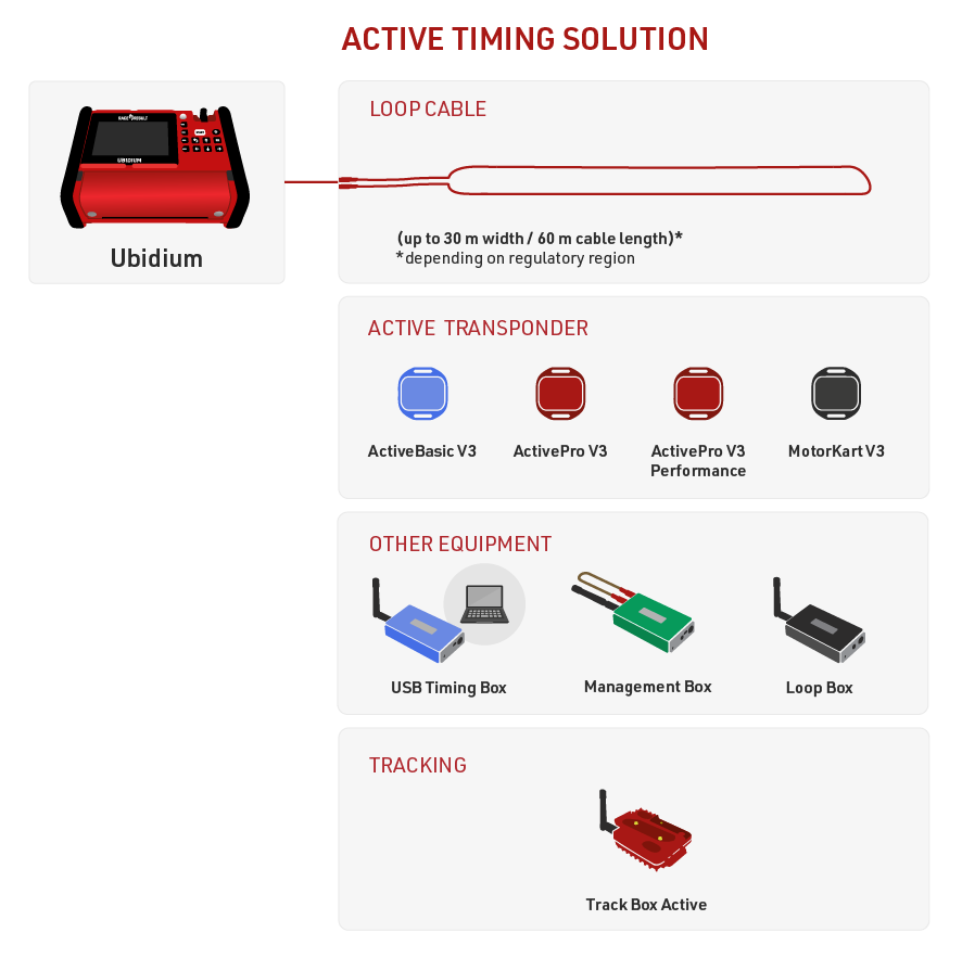
Active timing is possible with Ubidium, RACE RESULT Decoder with an Active Extension or using the standalone USB Timing Box.
The Loop Box provides additional flexibility to the setup, it can be run as a standalone timing point, but must be used with one of the main Active systems to receive the data either wirelessly via 2.4 GHz or from Store Mode on the transponder.
The Track Box Active uses 2.4 GHz to receive trackpings from transponders (when activated), and does not rely on any additional loop cable. Track Boxes contain a different algorithm for calculating times and so offer lower precision and should not be used in areas where participants may be stationary for prolonged periods of time (such as Triathlon transition zones).
USB Timing Box
The RACE RESULT USB Timing Box allows you to replace the Decoder and Active Extension with a single USB connection to your PC.
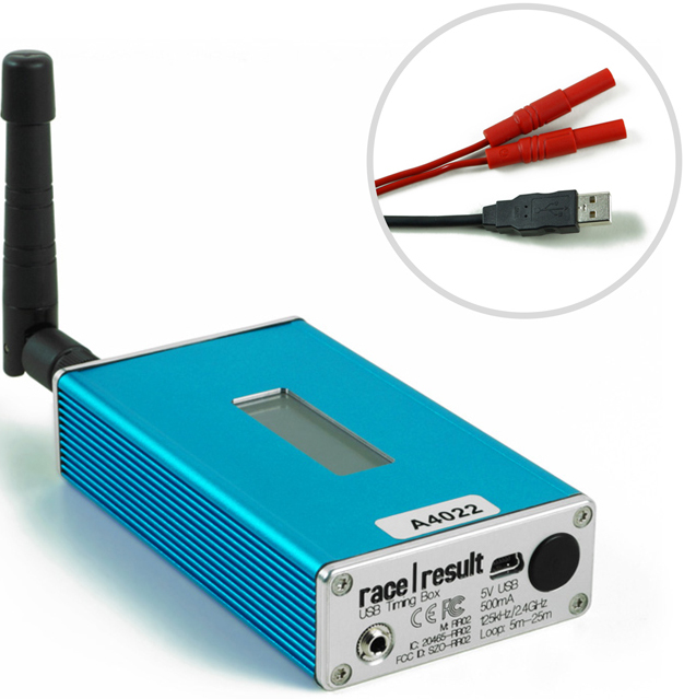
The USB Timing Box can be used to time sporting events, scan tags at race pack pickup, or for just about any other application: the open-source software of the USB Timing Box allows you to develop any solution that may have nothing to do with sports timing.
The USB Timing Box is compatible with our Loop Box where the USB Timing Box can receive passings from a Loop Box in Repeat Mode. The USB Timing Box does not include additional functionality such as a 3G connection or GPS time synchronization.
Turning USB Timing Box on/off
To turn the box on, press and hold the button until the center red LED turns off and a boot screen is displayed with information about the system.
To turn off, press the button once. The screen will display the following:
| press again: OFF |
| hold for config |
Press the button again to turn off.
The box will also turn on automatically when connected to via USB and cannot be switched off.
When disconnecting the USB, the device will automatically shut down if there is no loop connected and no passings have been recorded on the device since it was started.
USB Timing Box Configuration
The USB Timing Box has the same settings as the Active Extension: Loop Power, Channel ID, Loop ID. Additionally, the Mode can be set.
The box can be configured by pressing the button for 2 seconds. The first of the four settings will start blinking and can be changed by pressing the button again. By pressing the button again for 2 seconds, the setting will be confirmed and the next setting can be changed. To exit navigating menus, continue holding down the button until no setting blinks anymore.
In this example, the Loop ID is being changed:
| Loop█ 1 020% < |
| CH# 8 TIME |
USB Timing Box Modes
Timing
In this mode, the USB Timing Box operates as a primary timing device. Times from transponders are received and can be read out via the USB serial connection.
It can additionally receive passings from Loop Boxes in Repeat Mode or Stored Passings from transponders.
Kiosk
Kiosk is intended for when the USB TIming Box should be used for short range applications such as race pack collection or transponder assignments. In Kiosk mode the 2.4Ghz sensitivity is greatly reduced and it is anticipated that only detections from transponders within ~30 cm of the device will be received.
Note that the 2.4Ghz antenna must be connected in order to use Kiosk mode, without the antenna then the sensitivity will be too low to receive any detections.
Repeat
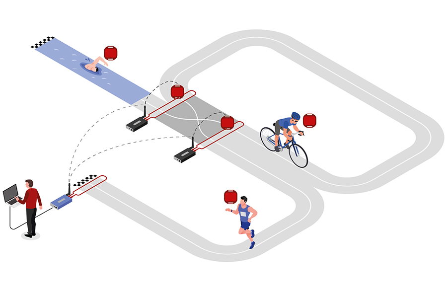
In this mode, the USB Timing Box activates the transponder, receives its data and sends (repeats) it to a primary system.
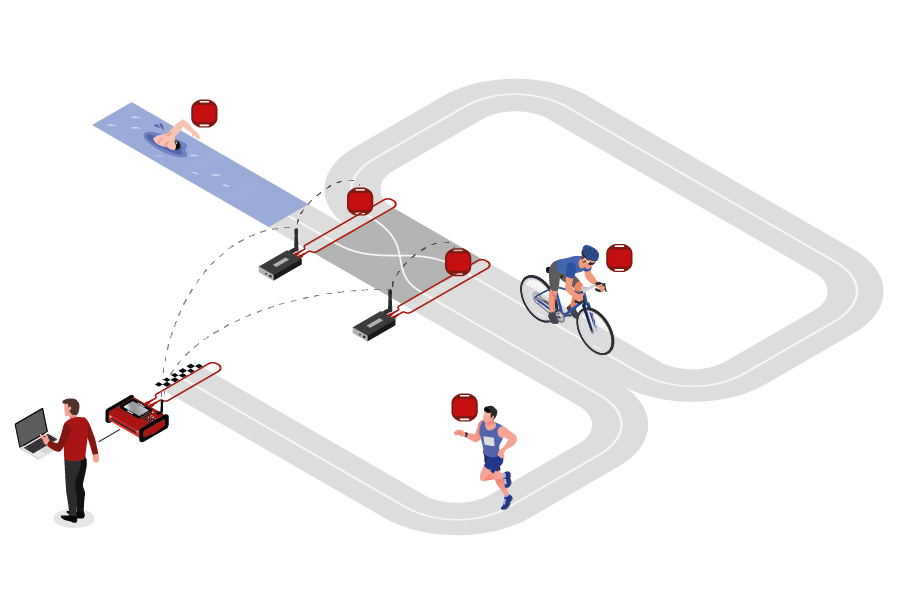
This is an easy way to connect several timing points within an area, e.g. a triathlon finish, transition in and transition out. The maximum distance between repeating / receiving devices can be up to 900 m depending on conditions.
Note that the USB Timing Box has an internal buffer for 1000 detections. Even if the connection between devices is interrupted, the detections will not be lost: once the connection is recovered, the USB Timing Box will transmit the buffered detections. Thanks to the precise internal clock of the device, the detection time will still be correct and precise.
For the communication between devices when using Repeat Mode please note:
- Devices need to run on the same channel (see Channel ID Setup). It is recommended that you select a fixed channel on the main system instead of using the auto mode.
- The main loop that will receive the detections from the devices in Repeat Mode must have Loop ID 1. This way the devices know where to send the data even if several systems are present.
Whilst in Repeat mode USB serial communication is disabled, however the port can still be used to provide power.
Store & Copy (FW2.5 and above)
This mode only works with the ActivePro and MotorKart transponders, V2 transponders may additionally return less accurate times.
In this mode, when the transponder is activated by the USB Timing Box, it will create a stored passing on the transponder and additionally send a copy of the time to the USB Timing Box. The passing which is received by the USB Timing box can then be read out via the USB Serial connection as normal.
Additionally note that the copied passing may have lower accuracy than the stored passing or regular Timing Mode, as the internal calculation and communication prioritises the stored passing.
Display Explained
The display of the USB Timing Box can have the following indications:
|
USB Timing Box when it is in Timing mode and connected via USB to a computer. The moving icon in the top right corner indicates that a Loop is connected. The bottom right section of the screen will flash between these two screens. The top screen shows the battery indicator. The bottom screen shows the USB voltage. A range between 5.0V and 4.5V is good. |
||||
|
USB Timing Box when it is in Timing Mode and on battery power. The "19h" displayed in the bottom right corner indicates the time until zero battery in hours. |
||||
|
USB Timing Box when it is in Store&Copy mode and connected via USB to a computer. Store&Copy mode is indicated by an S in the display. |
||||
|
USB Timing Box when it is in Repeat mode and connected via USB to a computer. Repeat mode is indicated by an R in the display. In Repeat mode the USB connection allows charging the device but no data communication. The antenna symbol in the bottom left indicates a wireless connection to the receiving device (Loop# 1 on the same Ch#) |
||||
|
USB Timing Box when it is in Kiosk Mode and connected via USB to a computer. The K indicates Kiosk Mode. |
USB Connection
The USB Timing Box easily connects with the Transponder Module and Timing Module. Your PC should have the appropriate USB drivers to connect to the USB Timing Box. If this not be the case, please see Troubleshooting for instructions on installing Windows drivers.
Ensure that the TagReaderKeyboard and TagTool software are not open when the Transponder Module is connecting with the USB Timing Box. As they use virtual COM ports to connect to the USB Timing Box, it cannot connect to two applications at the same time.
Online Firmware Update
It is recommended to update the firmware when a new firmware is available. See Firmware Release Notes.
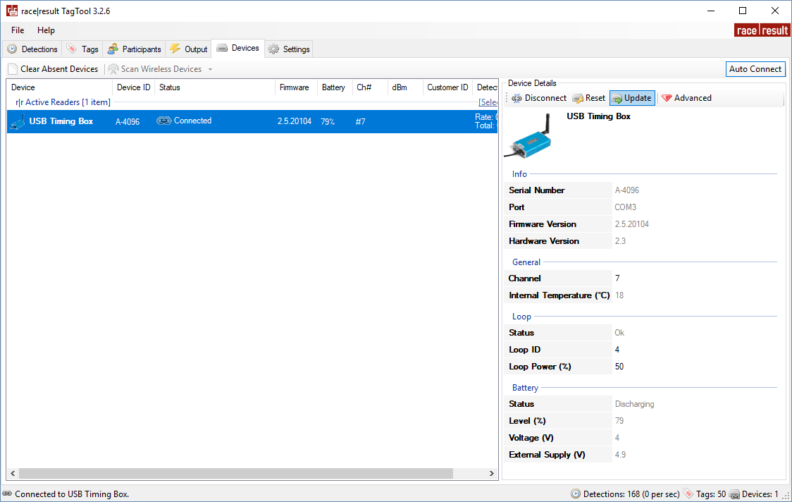
For firmware updates for the USB Timing Box and USB Management Box open your TagTool and connect your device, the most recent Active Device firmware is included in the most recent release of TagTool. Once it is connected, select the device you wish to update then click Update in the Device Details window, and select the most recent firmware version (highest value name). It is important that you do not unplug the device during the update.
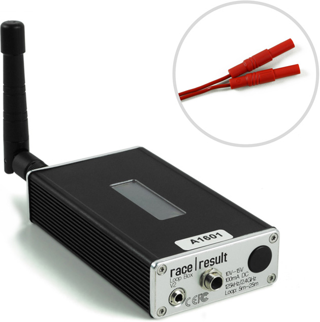
Loop Box
The Loop Box is an additional stand-alone device which activates the active transponder, but does not process the data of the transponders. Instead, the passing data will either be repeated to another box or be stored in the transponder.
In this section, the USB Timing Box and Active Extension will be referred to as the main loop.
Turning Loop Box on/off
To turn the box on, press and hold the button until the center red LED turns off and a boot screen is displayed with information about the system.
To turn off, press the button once. The screen will display the following:
| press again: OFF |
| hold for config |
Press the button again to turn off.
The box will also turn on automatically when connected to an external power supply and cannot be switched off.
When disconnecting from an external power supply the box will automatically shut down if there is no loop connected and no passings have been recorded on the device since it was started.
Loop Box Configuration
The Loop Box has the same settings as the Active Extension: Loop Power, Channel ID, Loop ID. Additionally, the Mode can be set.
The box can be configured by pressing the button for 2 seconds. The first of the four settings will start blinking and can be changed by pressing the button again. By pressing the button again for 2 seconds, the setting will be confirmed and the next setting can be changed. To exit navigating menus, continue holding down the button until no setting blinks anymore.
In this example, the Loop ID is being changed:
| Loop█ 1 020% < |
| CH# 8 Repeat |
Loop Box Modes
Repeat Mode
In this mode, the Loop Box activates the transponder, receives its data and sends (repeats) it to a primary system.
This is an easy way to connect several timing points within an area, e.g. a triathlon finish, transition in and transition out. The maximum distance between repeating / receiving devices can be up to 900m depending on conditions.
Note that the Loop Box has an internal buffer for 1000 detections. Even if the connection between Loop Box and the main loop is interrupted, the detections will not be lost: once the connection is recovered, the Loop Box will transmit the buffered detections. Thanks to the precise internal clock of the Loop Box, the detection time will still be correct and precise.
For the communication between devices when using Repeat Mode please note:
- Loop Box and the main loop need to run on the same channel (see Channel ID Setup). It is recommended that you select a fixed channel on the main decoder instead of using the auto mode.
- The main loop that will receive the detections from the Loop Box(es) must have Loop ID 1. This way the Loop Boxes know where to send the data even if several systems are present.
Impulse Mode
The Impulse Mode is the same as Repeat Mode, but the audio output will be used as impulse input that creates a fake detection.
Store & Forward (FW2.6 and above)
This mode only works with the ActivePro and MotorKart transponders, V2 transponders may additionally return less accurate times.
In this mode, when the transponder is activated by the Loop Box, it will create a stored passing on the transponder and additionally send the passing to the device.
For each stored passing an internal timer on the transponder is started which can then later be converted into a time, the stored passing maintains the loop information of the device which activated the transponder. The internal clock for each stored passing runs for a maximum of 24 hours (passings will be deleted afterwards) and a maximum of 64 passings can be saved.
When the transponder is activated by another active system which is not in Store & Forward or Store mode then the transponder will transmit not only the new passing but also all stored passings.
For the forwarded passing to be received you will need to follow the same guidelines for communication as per Repeat mode.
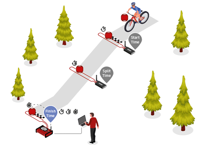
For example for a MTB downhill race, a Loop Box at the start and split could create stored passings on the transponder, and at the finish three detections will be received (start, split and finish).
Should the start or split Loop Boxes be in range of the finish, then these will be received immediately. If, however, the connection drops out during the race, passings will still be stored on the transponder and will then be received at the finish.
When using Store & Forward mode, if you receive both the forwarded passing and the stored passing then the Active system may not store two records in the passings file. For every incoming passing the system checks within the most recent 1,000 passings if it received another passing with the same Wake Up Count. If so, then the later one will be ignored as it is considered a duplicate.
Additionally note that the forwarded passing may have lower accuracy than the stored passing or regular Repeat mode, as the internal calculation and communication prioritises the stored passing.
Store Mode (FW2.5 and below)
Similar to Store & Forward mode, transponders will create a stored passing which can be read out at a later time.
With Store mode on Firmware 2.5 or earlier the passing is not additionally forwarded to the device, only the stored passing is generated.
Loop Box Time
Note that the Loop Box and the ActivePro/MotorKart transponder do have an internal clock, but do not need to have the current time of day. They simply tell the main loop how much time has elapsed since the detection occurred. The main loop will then calculate the detection time by subtracting this offset from its current time.
Loop Box Display
The display of the Loop Box can have the following indications:
|
Loop Box when it is in Repeat Mode and connected to mains power. Repeat mode is indicated by an R in the display. The moving icon in the top right corner indicates that a Loop is connected. The antenna symbol in the bottom left indicates a wireless connection to the receiving device (Loop# 1 on the same Ch#) is established. The bottom right section of the screen will flash between these two screens. The top screen shows the battery indicator. The bottom screen shows the voltage. A range between 11.5V and 12.0V is good. |
||||
|
Loop Box when it is in Repeat Mode and on battery power. The "19h" displayed in the bottom right corner indicates the time until zero battery in hours. |
||||
|
Loop Box when it is in Store&Forward Mode and running on battery. Store&Forward mode is indicated by an S in the display. The antenna symbol in the bottom left corner indicates a connection to a main system is established and passings are forwarded in additional to the stored detection. |
||||
|
Loop Box when it is in Impulse Mode and connected to mains power. The functionality is identical to Repeat Mode, except for the 3.5mm jack which functions as a Trigger In. Impulse mode is indicated by an I in the display. |
Receiving Loop Box Data and monitoring the connection using RACE RESULT 14
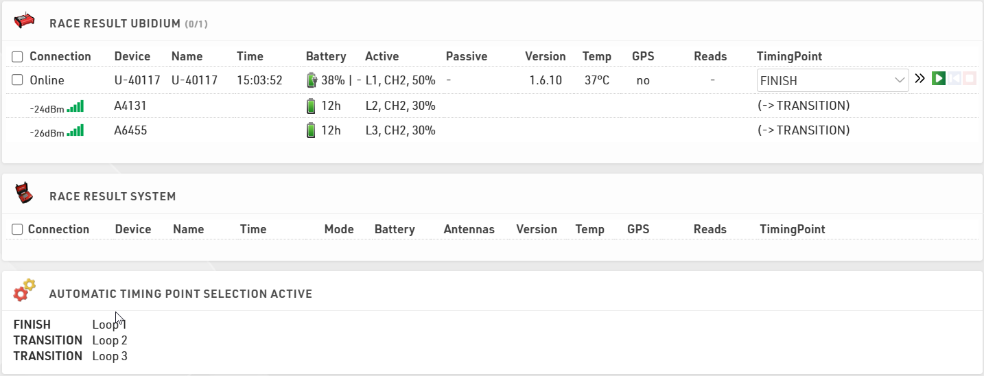
When using one or more Loop Boxes in Repeat Mode, the detections from several timing points will be received through the base (Loop ID 1) Ubidium or RACE RESULT System with Active Extension or USB Timing Box, and be read in the Timing tab through one single connection.
To assign detections from a certain loop to a certain Timing Point in the software, go to the Timing points settings in the Timing tab in your event file, and define the Automatic Timing Point Selection settings. The below screenshots show a typical setup of a triathlon event, the main system at the finish line is set to loop 1 (base), the two Loop Boxes at the entrance and exit of the transition area are set to loop 2 and loop 3 respectively.
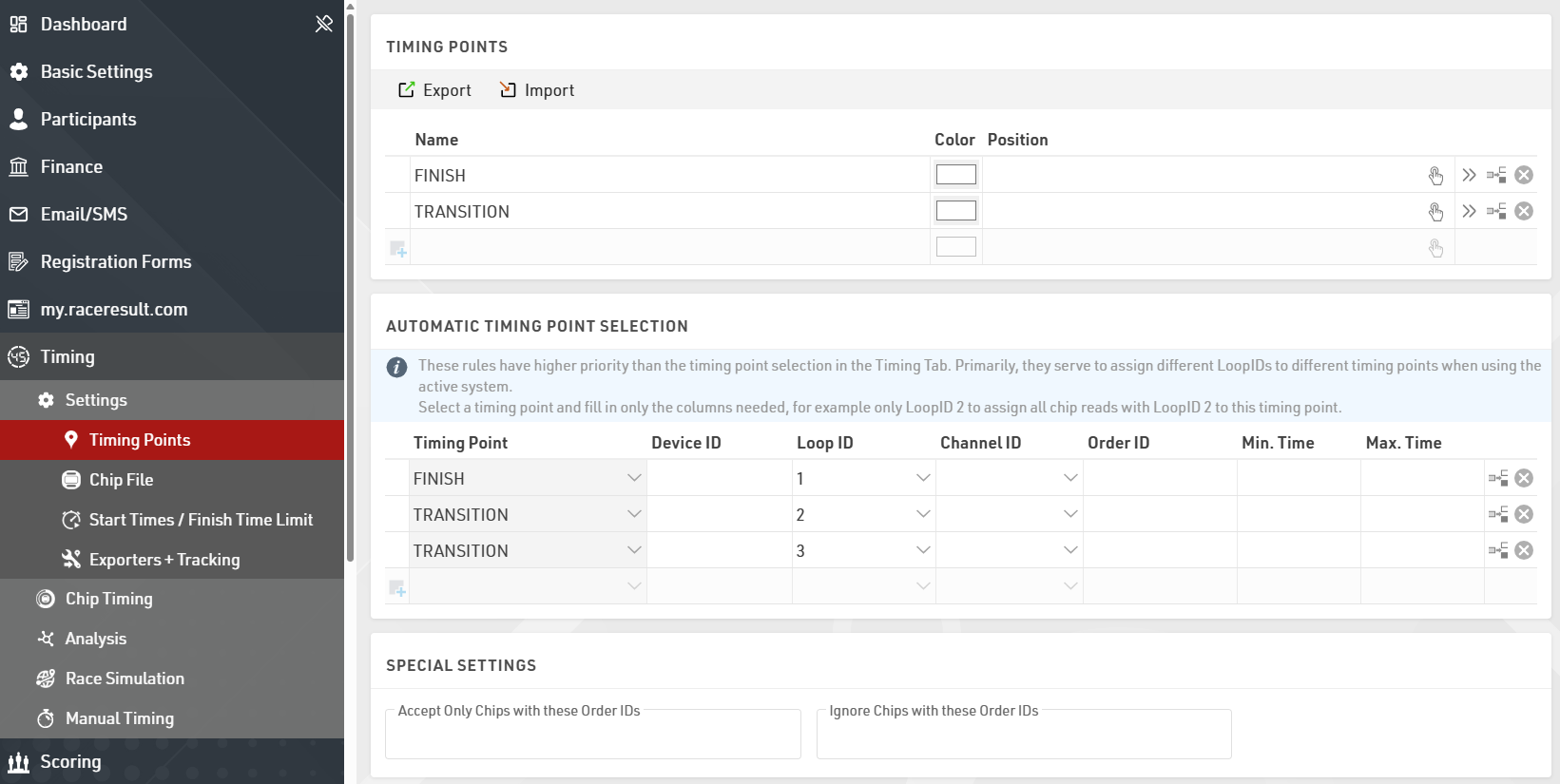
In the Chip Timing and Systems section of the Timing tab, the Loop Boxes are listed under the main system they are connected to, with an indication of the signal strength and of the battery status. On the far right, the software displays which timing point the data of the Loop Box will be written in, if an automatic timing point selection rule applies. For the main system, note that you do not necessarily need to select a timing point in the drop down selection menu if you have set up a rule that applies to that channel and loop ID combination. The automatic timing point selection rules have priority over the dropdown selection.
Here is a table indicating the estimated quality of the signal based on the value displayed:
| Quality | Value |
| Perfect (could not be better) | above -65 dBm |
| OK (nothing to worry about) | -75 dBm, ... , -65 dBm |
| Not Great (still working, but could be better) | -85 dBm, ... , -75 dBm |
| Barely Detected (setup should be checked) | below -85 dBm |
Active Extension
The Active Extension connects to the feature port of the RACE RESULT Decoder in order to operate as an active system.
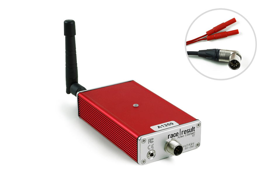
The Active Extension does not have a screen and is entirely controlled by the decoder. When in use the time base of the decoder is managed by the Active Extension which contains a more precise internal clock.
The Active Extension can be used with data cables up to 30m in length, allowing the decoder to be positioned further away from the timing point. It can also be used with the Loop Box to receive passings transmitted by repeat mode, or receive passings which were stored on the transponder.
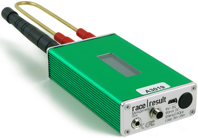
Management Box
The Management Box is a key piece of equipment for efficiently managing your active transponders. It also allows you to place your ActivePro / MotorKart transponders into deep sleep mode which can save 40% of the energy used by the transponders.
The Management Box is also used to active tracking mode on ActivePro / MotorKart transponders when being used with Track Boxes.
Turning Management Box on/off
To turn the box on, press and hold the button until the center red LED turns off and a boot screen is displayed with information about the system.
To turn off, press the button once. The screen will display the following:
| press again: OFF |
| hold for config |
Press the button again to turn off.
The box will also turn on automatically when connected to an external power supply, either via USB or the 12 V power connector. When connected to power the device cannot be switched off.
When disconnecting from an external power supply the box will automatically shut down if there is no loop connected and no passings have been recorded on the device since it was started.
Management Box Configuration
The Management Box has several Modes which can be set for different functions, additionally the Loop Power can be adjusted and for Tracking mode the Channel ID and Start/Stop must be set.
The box can be configured by pressing the button for 2 seconds. The first available setting will start blinking and can be changed by pressing the button again. By pressing the button again for 2 seconds, the setting will be confirmed and the next setting can be changed. To exit navigating menus, continue holding down the button until no setting blinks anymore.
In this example, the mode is being changed (currently in Tracking mode):
| Start 100% < |
| CH# 8 █RACK |
The solid segment will be flashing to indicate which setting is being changed.
Management Box Modes
Kiosk (FW2.6 and above)
Kiosk is intended for when the Management Box should be used for short range applications such as race pack collection or transponder assignments. In Kiosk mode the 2.4Ghz sensitivity is greatly reduced and it is anticipated that only detections from transponders within ~30 cm of the device will be received.
Note that the 2.4Ghz antenna must be connected in order to use Kiosk mode, without the antenna then the sensitivity will be too low to receive any detections.
Check
Check mode primarily works with TagTool on your computer running on your computer. Here you can compile a list of your transponders, check the battery level of the transponders, and create a chip file for your events.
When in Check mode, the management box will only send a single detection for each transponder code until the device is restarted, note however that the device LED may blink multiple times for each detection.
Check mode can be used to quickly check for any Low Battery transponders in your pool, scan the transponders and check if the display shows LBAT: XX. In this case, XX defines how many transponders have a battery voltage of 2.3V or below.
Deep Sleep
Deep Sleep mode is used to activate Deep Sleep on transponders which lowers their sensitivity thus preserving battery life.
To ensure all transponders are properly set it is recommended to arrange your transponders into trays of a known quantity, scanning each tray individually and cross reference the counter in the top left corner of the display.
To wake transponders from Deep Sleep Mode simply requires the transponder to be scanned by any active device. In Deep Sleep Mode the transponder is less sensitive and requires more hits in order to wake up, so it is recommended to do this before your event to ensure all transponders are woken up.
Track
The Track mode lets you enable and disable tracking mode on your transponders.
In the upper left corner of the display you can switch between START to activate tracking, or STOP to deactivate it.
For complete information and tracking best practices, please read this article about Transponder tracking activation.
Management Box Display
The display of the Management Box can have the following indications:
|
Management Box in Check Mode, indicated by a C, and connected via USB to a computer. The moving icon in the top right corner indicates that a Loop is connected. The top left shows the number of unique transponders read. The bottom left displays the last read transponder code. The bottom right section of the screen will flash between these two screens. The top screen shows the battery indicator. The bottom screen shows the USB voltage. A range between 5.0V and 4.5V is good. |
||||
|
Management Box when in Tracking mode and running on battery. The moving icon in the top right corner indicates that a Loop is connected. The top left section toggles between START (or STOP - depending on the mode), to indicate the Tracking START (or STOP) mode and the number of unique transponders read and with Tracking enabled (or disabled). The bottom left shows the Channel ID on which Tracking will be activated. The bottom right shows the remaining battery expectancy of 12 hours. |
||||
|
Management Box when it is in Kiosk Mode and connected via USB to a computer. The K indicates Kiosk Mode. |
||||
|
Management Box in Deep Sleep Mode, indicated by a D, running on battery with a remaining battery expectancy of 19 hours. The top left shows the count of transponders set to Deep Sleep. The bottom left shows the last read transponder code. |
Firmware Update
It is recommended to update the firmware when a new firmware is available. See Firmware Release Notes.
For firmware updates for the USB Timing Box and USB Management Box open your TagTool and connect your device, the most recent Active Device firmware is included in the most recent release of TagTool. Once it is connected, select the device you wish to update then click Update in the Device Details window, and select the most recent firmware version (highest value name). It is important that you do not unplug the device during the update.
Active Setup
The active system consists of 2 key elements that must both be set up correctly, the Loop Cable and the 2.4GHz antenna for receiving data.
Loop Cable Set up
In most cases, the cable loop will be laid on the ground and either taped down with duct tape or covered by a mat.
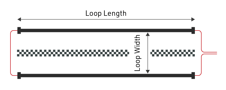
The loop cable should form a rectangle with a width of between 30cm and 60cm, with the exact line on which you wish to record a time positioned across the middle of the length of the loop.
Where possible use a loop of exactly the required length, at all times avoid coiling any excess loop cable since this can cause interference resulting in transponders not being activated. Loop cables cannot be installed on metal surfaces, these will completely inhibit the loop signal meaning no passings will be generated.
Loops can be buried in the ground, particularly for motorsports or on soft surfaces, when doing so it is common practice to protect the loop using some sort of pipe.
Loop Width
If you require higher precision, the loop should be narrower, and greater care must be taken to set up the loop precisely. Note that 0.01 second means only 5cm distance at 70km/h. So aligning the loop a few centimeters askew will have a negative effect on precision.
A wider loop, on the other hand, will result in higher read height but may lower precision. This is usually the preferred setup since most sports requiring the greatest precision require a PhotoFinish camera for verification.
In general, you should only make your loop narrower if you are confident that all transponders will be mounted at the same height (below 100cm or 50cm for MotorKart) and the maximum speed is also below 100km/h, this should also then be complemented by a lower Loop Power to maximise accuracy.
2.4GHz Antenna
The 2.4GHz antenna is used to communicate with the transponder, this is how the system receives the exact passing time from the transponder. It is critical that there is a clear line-of-sight between transponders and the 2.4GHz antenna, and the antenna must be used at all times.
In the event that the Active Extension has an obscured view of transponders then it may be necessary to use an Active Range Extender, this is a higher gain antenna, fitted to a longer cable allowing the antenna to be mounted higher and away from interference.
Note that the additional gain of the antenna is lost in the length of the cable and so simply setting up the range extender on the ground in the same position will have no additional benefit.
Antennas should be mounted pointing vertically upwards and kept away from metal as much as possible since this can interfere with the signal.
Possible Loop Issues
Active devices monitor the status of the loop constantly and can report the following loop issues which will be shown in the display of the decoder:
Loop Error
The loop is not connected anymore or has been cut. This error will be signaled by the RACE RESULT System with a long beep sound.
| Count: 3823 | Time: 11:40:23.323 | ZZZZZ01 |
| File No: 298 | IP: 192.168.1.202 | ZZZZZ01 |
| Upload: off | LOOP ERROR | ZZZZZ01 |
| USB: n/a | Battery: ██████__ | ZZZZZ01 |
|
|
Loop Limit
The system cannot provide enough power for the selected loop power. Either the cable is too long or too thin. The Loop Power which has been set will still be delivered, however the user should expect a reduced read height.
| Count: 3823 | Time: 11:40:23.323 | ZZZZZ01 |
| File No: 298 | IP: 192.168.1.202 | ZZZZZ01 |
| Upload: off | LOOP LIMIT | ZZZZZ01 |
| USB: n/a | Battery: ██████__ | ZZZZZ01 |
|
|
High Noise
The average noise over the 2.4GHz channel is higher than a determined threshold, suggesting that you should select a different channel. It will not drastically affect the precision of transponders, as the 125kHz channel is used to time the transponder. Transponders will keep trying to send their packets for one second after the detection when the channel is noisy or busy. ActivePro and MotorKart transponders will store passings if it fails to send the passing.
If the warning continues to be shown, the user should change the channel ID of the device.
| Count: 3823 | Time: 11:40:23.323 | ZZZZZ01 |
| File No: 298 | IP: 192.168.1.202 | ZZZZZ01 |
| Upload: off | HIGH NOISE | ZZZZZ01 |
| USB: n/a | Battery: ██████__ | ZZZZZ01 |
|
|
Overflow
Transponders are being detected faster than they can be sent to the decoder. The Active Extension has an internal buffer for 1000 detections. Should this buffer be full, detections will get lost and the decoder will show the Overflow error.
| Count: 3823 | Time: 11:40:23.323 | ZZZZZ01 |
| File No: 298 | IP: 192.168.1.202 | ZZZZZ01 |
| Upload: off | OVERFLOW | ZZZZZ01 |
| USB: n/a | Battery: ██████__ | ZZZZZ01 |
Active Settings
The following settings are applied to all Active timing devices, and are important to ensure reliable and accurate operation whilst timing.
Refer to the individual device guides to understand how to set the values on the corresponding device.
Channel ID
The communication (back channel) from the transponder to the decoder operates on 2.4 GHz which is a worldwide public band also used for many purposes, such as Wi-Fi.
Within this band, the active system can use 8 different frequency channels. When the loop activates the transponder, it also encodes the channel ID on the loop signal so that the transponder knows on which channel the decoder is listening for the reply from the transponder.
It is advisable to always use the channel with the least noise / interference, for this you can run a channel scan on whichever system you are using. Additionally, when using multiple systems you should try to keep these on different channels, particularly when in close proximity.
Backup Channels
Active Transponders from V2 and above (except ActiveBasic before 2023) use a primary and backup channel for sending passing data to the Active Extension, this can help in areas where there is high noise on the 2.4 Ghz frequency.
Additionally ActivePro V3 Performance transponders support Quad Channel Backup.
Loop ID
When activating a transponder, the loop also transmits a Loop ID. When transmitting the detection back to the decoder, the transponder will also transmit this Loop ID. This way, several active systems can run on the same channel: decoders within an area will 'hear' the detections from all loops but only process those from transponders that have been activated by their own loop.
It is common practice that your primary timing points will use Loop ID 1, this is the designator that this device is the central timing point.
When working with Loop Boxes set to Repeat Mode, it is critical that the device which should receive those passings is set to Loop ID 1, this identifies this system as the base system for that channel and only Loop ID 1 will receive passings from additional devices.
Loop Power
Simply put - the more power you put on the loop, the higher the transponder will read. Note that with ActivePro V1 / V2 transponders this can also result in reduced accuracy.
Depending on the type of sport, choose an appropriate value for Loop Power. For example for cycling (high precision needed, transponder fixed on the bike, thus close to the loop) choose a low value like 20%. However, if participants wear the transponder on the wrist and can finish with their arms raised, choose a high loop power like 80% or 100%.
Depending on what materials are underground at the timing point, the maximal read height with 100% loop power is 2-2.5 meters. Metal in the ground will reduce the read height.
You can see some guidelines for loop width / loop power and the resulting max detection height here
Active Detection Data
With each read the system saves some useful information about the passing, understanding this can help to better interpret your data and identify potential problems.
Since Active Transponders contain more onboard circuitry and communicate on the 2.4GHz channel they are able to store and send more information with each passing, understanding the Hits / RSSI values is also slightly different as explained below.
- Hits - The number of times the transponder has seen the loop pattern (which is repeated at 150 times per second), up to the strongest Loop Strength.
- RSSI (only useful for V2 Transponders and beyond, not applicable to Basic Transponders) - There are two radio links involved, 125kHz Loop and 2.4GHz Antenna for data communication. We want to know the quality for both, which is why the system reports two values packed into one figure.
- X refers to the 2.4Ghz received signal strength where -90dBm is the weakest and -58dBm is the strongest signal
- Y refers to the Loop power where 1db is the weakest and 16db is the strongest.
- Loop - The Loop ID of the device which recorded the passing.
- Channel - The Channel ID of the device which recorded the passing.
- WUC - Wake-Up-Count of the transponder is the number of times the transponder has been activated by a loop.
- Batt - The battery voltage of the transponder, we recommend retiring transponders with < 2.2v.
- Temp - The internal temperature of the transponder.
- SFlag - Will be between 64 and 127, or greater than 192, if the passing was stored on the transponder or the V3 Transponder issued a warning.
| Guidelines for detection strength | Hits | 2.4GHz RSSI (X) | 125kHz Loop (Y) |
| Perfect (could not be better) | 20..60 | better than -75dBm (-58dBm best for passing) |
8dB...16dB |
| OK (nothing to worry about) | 10...20 | -80dBm...-70dBm | 6dB...10dB |
| Not Great (still working, but could be better) | 5...10 | -85dBm...-75dBm | 4dB...8dB |
| Barely Detected (setup should be checked) | 1...5 | -90dBm...-80dBm | 1db...4dB |
How to improve detection quality:
- 2.4GHz: Make sure the receiving antenna has a direct line of sight to the transponder. If this is not the case, try replacing the receiving antenna (elevating it) and/or use our Range Extender.
- 125kHz: Make sure there is a direct line of sight between the loop and the transponder. When mounting the transponder on metal/carbon, please use our Chip Holders to leave some space between the transponder and metal. Also check the loop width, loop power (detection height) and transponder placement.
Calculation of RSSI Values
Active Box FW 2.4 and older: This value represents the maximum loop strength (Loop_Strength, see below) a transponder saw while recording the passing.
From FW V2.5 and newer: This value represents both, the maximum loop strength and the 2.4GHz strength the passing was received by the Active Box. The 8-Bit Value is divided bitwise XGGGLLLL (x must be ignored, G = 2.4GHz, L = Loop)
- 2.4GHz_Strength = -90 + 4 * GGG [dBm]
2.4GHz received signal strength at Box Antenna where -90dBm is the weakest and -58dBm is the strongest signal - Loop_Strength => 1 + LLLL
Loop Power in positive dB values from 1..16 where 1 is the weakest and 16 is the strongest
Examples:
16: 00010000 => 2.4GHz=-90+1*4 [dBm] and Loop=1+0 => -86dBm/1
77: 01001101 => 2.4GHz=-90+4*4 [dBm] and Loop=1+13 => -74dBm/14
Technical Specifications
Dimensions & Standards |
|
|---|---|
|
Regulatory Conformity and Standards |
EN60950 (safety) CE, RoHS, FCC |
| Operating Temperature | -30°C to 70°C |
| Dimensions | 27mm x 66mm x 117mm |
| Active Extension | |
|
Protection Class (with data cable / antenna connected) |
IP67 -waterproof- |
| Weight | 190g |
| USB Timing Box | |
|
Protection Class (with cable / antenna connected) |
IP52 - water resistant- IP54 with bumper usage |
| Weight | 266g |
| Loop Box | |
|
Protection Class (with cable / antenna connected) |
IP52 - water resistant- IP54 with bumper usage |
| Weight | 272g |
| Management Box | |
|
Protection Class (with cable / antenna connected) |
IP52 - water resistant- IP54 with bumper usage |
| Weight | 274g |
RF Characteristics |
|
|---|---|
|
2.4GHz Channel Frequencies - Main / Backup (Worldwide compliance) |
1: 2.480MHz / 2.410MHz 2: 2.405MHz / 2.470MHz 3: 2.425MHz / 2.465MHz 4: 2.475MHz / 2.440MHz 5: 2.415MHz / 2.445MHz 6: 2.460MHz / 2.430MHz 7: 2.435MHz / 2.455MHz 8: 2.450MHz / 2.420MHz |
| 2.4GHz TX Power |
17.5dBm |
|
Loop Frequency & Data |
125KHz Data packet = Loop ID + Channel Packet Rate: 150Hz OOK-modulation, Manchester encoded, 16-bit anti-false-wakeup pattern |
| Loop Power | 100% = 250mA RMS regulated peak current |
| Loop Cable & Length |
5m - 25m, >0,5mm² standard 4mm banana plugs |
Detections |
|
|---|---|
|
Max Read Range 25% Loop Power 100% Loop Power |
60cm (2ft) 2.5m (8ft) |
| Active Extension | |
|
Transponder Read Rate |
>100 transponders per second burst for 20 seconds >50 transponders per second continuously |
| Internal Data Buffer | 1,000 passings |
| Forewarn Data Delay | 100ms (from entering the loop center) |
| Max Passing Data Delay | 250ms (after loop center) |
| Repetitive Passing Rate Over Loop | 1 per second |
| Clock Stability |
24/1,000th second per day 0.28ppm TCXO calibrated to rubidium frequency standard traceable to NIST |
| USB Timing Box | |
|
Transponder Read Rate |
>100 transponders per second burst for 20 seconds >50 transponders per second continuously |
| Internal Data Buffer | 1,000 passings |
| Loop Box | |
| Transponder Read Rate* | up to 40 transponders per second continuously |
| Passing Transmission Delay | 200ms - compensated |
| Maximum Repeat Range | 900m with direct line of sight |
| Internal Data Buffer | 1,000 passings |
| Management Box | |
|
Transponder Read Rate |
>100 transponders per second burst for 20 seconds >50 transponders per second continuously |
| Internal Data Buffer | 1,000 passings |
*Reduced to account for passing transmission in Repeat mode
Battery & Connections |
|
|---|---|
| Active Extension | |
| Data Cable |
5m (standard) 15m, 30m (optional) |
| USB Timing Box | |
| Battery | 4000mAh, 3.7v Li-Po |
|
Battery Life (Standalone Unit) |
12h - 20h dependent on Loop Power |
| USB 1.1 | 500mA |
| Loop Box | |
|
Battery |
4000mAh, 3.7v Li-Po |
| Battery Life |
12h - 20h dependent on Loop Power |
| Battery Charging |
10v - 15v, 1000mA (at 100% Loop Power) |
| AC Power Supply | 110v - 230v, 50 / 60Hz |
| Management Box | |
| Battery | 4000mAh, 3.7v Li-Po |
|
Battery Life (Standalone Unit) |
12h - 20h dependent on Loop Power |
| USB 1.1 | 500mA |
| Battery Charging |
10v - 15v, 1000mA (at 100% Loop Power) |
| AC Power Supply |
110v - 230v, 50 / 60Hz |
Serial Port Connection (USB Timing Box & Management Box) |
|
|---|---|
| Bautrate | 19200 bps |
| Stop Bit | 1bit |
| Parity | OFF |
| Databits | 8bits |
| Softflow-Control | OFF |
| Hardflow-Control | OFF |
| DTR-Line | Special Purpose |
Active System FAQs
Minimum distance between two loops
Sometimes you may want to set up 2 loops close to each other to measure speed at a certain point on the course, but it is important to know that a transponder has an internal dead time when it cannot be activated.
As such we suggest as a general guideline that the minimum distance between 2 loops is the MAX speed in km/h divided by 10. For example if you expect a max speed of 160 km/h (100mph) then a minimum distance of 16m between the 2 loops should be used.
Active System 2.4GHz Frequencies
The RACE RESULT active system communicates via the 2.4GHz frequency, there are 8 channels to choose from each with a unique frequency. Each channel also has a backup frequency, meaning it will switch between the Main and Backup Frequencies which aids transmission in environments where there is high noise.
The backup frequency is used by V2/V3 Transponders and up.
Old Decoder Firmware and FW 2.5 Active Boxes: When the channel switching of a decoder is set to AUTO it will automatically disable this when a V1 transponder is detected, this will only reset when the system is restarted. This is the recommended setting. Loop Boxes all use AUTO mode by default and this cannot be changed.
Ubidium and FW 2.6 Active Boxes: Permanently switch frequencies. Therefore use of V1 Transponders is not recommended.
| Channel | 1 | 2 | 3 | 4 | 5 | 6 | 7 | 8 |
|
Main Frequency [MHz]: |
2480 |
2405 |
2425 |
2475 |
2415 |
2460 |
2435 |
2450 |
| Backup Frequency [MHz] |
2410 |
2470 |
2465 |
2440 |
2445 |
2430 |
2455 |
2420 |
2.4GHz Test Mode (V2 Boxes FW 2.5 and up only)
The 2.4GHz Test Mode on the USB Timing Box, the Loop Box, and the Management Box allows advanced users to check channels for interference and make sure the 2.4GHz frontend and antenna are working correctly.
To get into Test Mode and check for noise:
- Ensure the device is switched off and has the 2.4GHz antenna connected.
- Press and hold the button, and continue to hold the button until the following screen is shown.
B RSSI=00 LQI=00 CH# 8 NOISE=02 - Press the button to cycle through the channels.
- Ensure that no transponders are activated and no other boxes nearby are operating on the same channel.
- Stay on each channel for at least 3 seconds. Look for the channel showing the lowest value for noise. Noise should show a value below 10.
- To return to normal operation, press and hold the button until the red LED turns on then release the button to resume normal startup.
- For timing purposes, set the box to the channel showing the lowest noise value.
Testing Box 2.4GHz performance (and antenna)
- Boot two boxes into test mode as above and set them to the same channel.
- Place them approximately 1m apart on a table.
- Ensure that no other boxes are on the same channel within connection range and no transponders are activated by the boxes.
- Point both the antennas upwards so that they are parallel to each other:
| B RSSI=65 LQI=55 |
| CH# 8 NOISE=33 |
With two V2 boxes, you should see a RSSI Value of at least 60, higher is better. If you see a RSSI value of 60 or better, you know that both boxes and both antennas are working OK.
Noise values can be ignored in this setup.
Testing a Transponder 2.4GHz performance:
Disconnect the loop and hold a transponder against the loop connector terminals to activate it. You should see similar values on the screen.
| T RSSI=75 LQI=55 |
| CH# 8 NOISE=33 |
You should see a RSSI Value of at least 75, higher is better. If you see a RSSI value of 75 or better, you know that the transponder and the box (and its antenna) is working OK.
Noise values can be ignored in this setup.
Testing 2.4GHz performance of an Active Extension:
The active extension does not support this test mode. But you can still test it (and its antenna) with a second box. Set the channel on the decoder to the channel you want to test on and follow the steps for testing a box.
Parameters:
Below is a description of each of the indicators on the screen:
|
Location on screen |
Description |
|
|
B/T |
Top left |
Indicates from what source the values on the screen are calculated from. B = Beacon = Other Box, T = Transponder |
|
RSSI |
Top center |
Received Signal Strength Indicator - measure of received signal power |
|
LQI |
Top right |
Link Quality Indicator (used for internal testing only) |
|
CH# |
Bottom left |
Channel ID |
|
NOISE |
Bottom right |
Noise level of channel |
Active High Noise Warning
A High Noise warning when using an Active Extension is triggered when there is large interference on the 2.4GHz channel which is being used, this can come from common things such as TV cameras, drones, wireless microphones, bluetooth or even public Wi-Fi hotspots. It may also be that the noise warning has been triggered by a Loop Box and so it is important to check your whole surrounding area.
Our 2.4GHz channels can be used alongside other devices on the same frequency, but if these are too strong or transmitting large bursts of data then it can interfere with the detections, with V2 Transponders the interference has been reduced by introducing a secondary backup frequency on all channels.
If possible you should remove the source of the 2.4GHz interference or move it away from your systems, if this is not possible then the channel scanner will show you the best channel to use in your current setup. If you do change channels on your Active Extension then don't forget to also change your Loop boxes and you may also need to change your automatic timing point selection in race result 11.
What Causes Loop Limit
Loop Limit means that the Active System was not able to apply the selected Loop Power to the attached Loop.
Think of a car: You push the pedal to the metal, but you are going up a hill and it can't go faster. The car knows that you would want it to go faster, but it can't.
Loop Limit is mainly caused by inductance of the loop which is determined by:
- to long loop cable
- to thin loop cable
- loop cable coiled up or wound around metal
- to much metal around the loop
With our standard length cable you should rarely see a loop limit. With everything longer you will get a loop limit if you request 100%. This is due to regulatory limits. On longer loops it is simply not allowed to have 100% loop power.
Detections with Invalid Loop ID / Channel ID
It can happen that an Active Transponder will generate a passing with an invalid Channel ID / Loop ID, these are most commonly received as stored passings due to the cause for triggering them. Normally these invalid passings have just a single hit and there are 3 possible causes that we have identified:
Corrupt Data From Loop
When on the edges of the loop field the data packet received by the transponder can be corrupted, this results in the Transponder storing a passing with the incorrect Channel / Loop ID and a single hit. This was fixed in V2 transponders from November 2017, the new configuration requires 2 hits for a valid passing.
Participants Standing on Loops (Swim Starts)
The most common time this happens is during rolling swim starts when participants are stood directly on or near the loop for long periods of time. This results in similar corrupt data packets as above which would normally be ignored but due to the rapid consecutive detections the transponder may incorrectly store an invalid passing. This can happen to any ActiveTransponder
External Interference
The 125kHz channel is not unique to RACE RESULT transponders, and transponders may sometimes be activated by external electrical interference such as power cables and store a passing, which could be from the day before. This rarely happens to new V2 transponders due to the new configuration but can happen to any transponder if the interference is strong enough to cause multiple hits.
Solutions
If you have older ActivePro V1 Transponders we offer a trade-in program to upgrade to V2 transponders which eliminate most of the invalid passings.
Your decoder has an option to discard all stored passings, if you are not working with stored passings then you could choose to discard stored passings, as these issues are always reported as stored passings then they will be discarded. Warning: You may lose valid detections which have been stored by the transponder which could not be transmitted directly to the Active Extension or Loop Box.
In firmware version 2.26 we introduced an option to discard all passings below X number of hits. We have found that nearly all invalid passings are reported with a single hit, so setting this to discard all passings below 2 hits can solve this, you can also set the value higher if you are seeing lots of invalid passings with more than 1 hit. WARNING: This will discard ALL passings with less than X hits, so if you do have valid detections with a single hit they will be lost, but if you have passings with low hits then you should check your setup as a single hit suggests there is a problem with the loop setup.
USB Device Errors
In the event your USB device (USB Timing Box or Management Box) is not recognised by Windows it may be necessary to manually install the drivers. This is not normally required, the drivers should be automatically installed, but in particularly old devices an error with the FTDI chip the firmware may not be correctly recognised or may be registered as "NON GENUINE DEVICE".
It is necessary to first completely uninstall the drivers before installing new ones so follow the below instructions accordingly and do not connect your USB device until instructed.
- Download CDM Uninstaller from FTDI
- Unzip the contents and right click CDMUninstallerGUI.exe and select Run as Administrator
- In the GUI ensure that Vendor ID is set to 0403 and delete the Product ID.
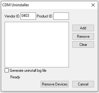
- Click Add and you should see a new item listed as below
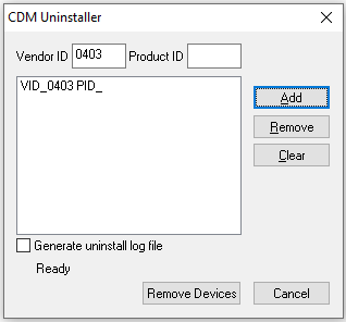
- Now click Remove Devices which will now uninstall all drivers for FTDI converters
- Once this is complete then restart Windows
- Download FTDI Drivers
- Unzip the folder and run the file labelled setup.exe
- Follow the install wizard to install drivers
- Once complete you can connect your USB Device and Windows will now install this using the correct drivers.
Active Boxes Expected Battery Life
Battery life for Loop Boxes, USB Timing Boxes, and Management Boxes varies based the loop power and the setup itself. Fully charged active timing boxes running firmware 2.6 (revision 39869) or newer firmware versions can achieve the following runtimes with a standard loop.
| Loop Power | Estimated Run Time |
| 20% | 25 hours |
| 30% | 25 hours |
| 40% | 24 hours |
| 50% | 23 hours |
| 60% | 22 hours |
|
70% |
20 hours |
| 80% | 18 hours |
| 90% | 15 hours |
| 100% | 12 hours |
Note: Energy consumption is highly dependent on your configuration. By optimizing the loop power setting, you can achieve more than double the operating time compared to always running at 100% power.