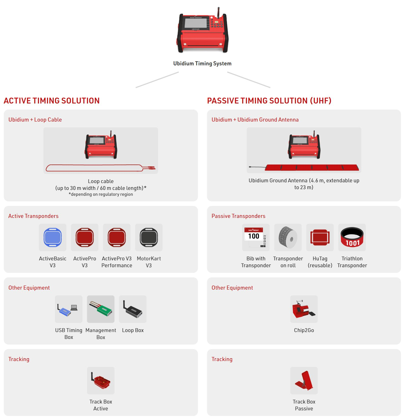
RACE RESULT offers a range of both Passive (UHF) and Active (125 KHz / 2.4 GHz) technology to provide best-in-class solutions for sports timing.
Which technology you choose for your event can depend on a number of factors such as speed, number of participants, level of accuracy required, timing point location / ground surface.
The Ubidium Timing System combines both Passive and Active technologies in one, and can even operate both simultaneously.
Passive (UHF) timing is typically used for mass participation events at lower speeds. The passive system primarily uses the Ubidium Ground Antenna which connects to the Expansion port of the system and can be extended up to 23m.
Additionally, the Track Box Passive can be used for low-density or remote timing points, and the High Gain Antenna can be used to create unobstructed finish lines or where a ground antenna cannot be used.
Active timing is most often used for multisport events, high speed sports or where it is not possible to use UHF. Active transponders contain a battery and so have a finite life span, but offer the highest accuracy and read rates of any transponder based timing system. An active system uses a loop cable which creates a 125 KHz electromagnetic field, and then the data communication uses 2.4 GHz.
Active Transponders also have a tracking feature which uses 2.4 GHz to emit TrackPings to the Track Box Active which does not require a loop cable. This mode is most useful for enhancing live results or tracking with additional data points, or for timing points where precision is not critical.
Ubidium

RACE RESULT Ubidium is the most advanced timing solution available on the market, capable of handling both Active and Passive (UHF) timing from a single system.
The Ubidium system is the core of Ubidium and is used to receive data from a range of different timing connections, such as Active Loops, Ubidium Ground Antenna or Impulse Devices, to generate passing data based on the highly-precise on-board clock.
System
The Ubidium System contains the main computing logic and interface for timing with Ubidium.
The system integrates all the components required including batteries and power management, the user-interface with display and keypad, 4G / LTE modem, ports for networking and connectivity, timing connectors and more. No external accessories are needed with Ubidium.
Ubidium stores all data on it's built-in memory, this can then be accessed by scoring software, such as RACE RESULT 12, or uploaded directly to a cloud-based server.
The system ensures uninterrupted operation as it runs independently from any other computer or external power supply.
Ground Antenna
The Ubidium Ground Antenna is the most advanced antenna for sports timing, and can only be used with the Ubidium System.
The standard configuration consists of 6 segments of 77cm each, giving a length of 4.6 m / 15 ft, and each segment contains an individual Ubidium Antenna Element.
The ground antenna can be shortened to a minimum of 2 segments (1.5 m / 5 ft) or extended up to a maximum of 30 elements (23 m / 75 ft).
Quick Start Guide
Your NEW Ubidium System
Inside your package you should find the following items:
- Ubidium System
- 1 x 98 Wh Ubidium Battery (Pre-Installed)
- 1 x AC Charging Cable
- 1 x 13 m Loop Cable
If you ordered additional accessories or spare parts they may be included separately.
Ubidium Overview

Powering On Ubidium
Ubidium has two battery compartments which are located on the lower front side of the system, each compartment is protected by a transparent plastic cover allowing you to always see the current state of the batteries on the integrated LCD display.

To open a battery compartment turn the center locking knob to align the cut-out edge with the compartment you wish to open.
The batteries can only be installed in the correct orientation with the groove facing upwards to align with the notch in the compartment opening.
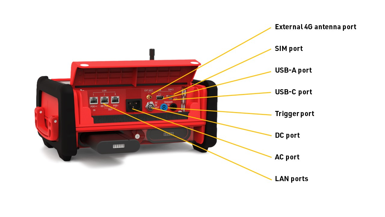
We advise fully charging your Ubidium system using the provided AC charging cable, which is plugged in to the AC Charging port below the port flap. The charging status of the installed batteries will be shown on the display even if the system is powered off.
To turn the system on, firmly press and hold the power button on the main keypad, until the status LED illuminates green.
Setting The Time
Ubidium contains a highly accurate Real-Time Clock inside which maintains an accurate time even when the system is powered off.
When starting up Ubidium will automatically search for GPS satellite signal in order to sync the clock with GPS time which provides the most accurate synchronisation available.
You will need to ensure that the Time Zone is correctly set on the system in order to have the correct local time, this is set through the time menu which can be accessed by pressing the first (top) navigation button on the right side the screen.
To change the time zone select the menu item which corresponds to Timezone by using the navigation keys to the right side of the screen.
Scroll up and down this menu using the arrow keys to find the correct time one for your location and press the OK button to store this.
Pressing the Back button will exit any open menus to return to the main timing display.
Connect To The Cloud
If you plan to use Ubidium as an online device to connect to RACE RESULT 12 you'll need to configure some basic settings to connect the system to your account.
From the main timing display, open the network menu by pressing the third navigation button to the right side of the screen.
Depending on how you will be connecting to the internet you may need to configure either the Ethernet, WiFi or Mobile settings in order to establish an internet connection, for more information see Ubidium Network Settings.
If you are using a RACE RESULT SIM card then simply insert this to the SIM port which is located under the flap and this will be automatically configured for you by the system.
Once online, select the Cloud menu item and from there you'll need to set the Customer Number to your RACE RESULT Customer ID. To change the number use the up and down arrow keys to change each digit, and right and left arrow keys to select the digit. Take care that if your Customer ID is less than 6 digits, then the first digit should be set to 0. Press OK once done to save the value.
Once the Customer Number is set, select Enabled and change the value to YES, you can also force this to automatically enable on startup if you choose to.
Start Timing
To start timing with Ubidium you simply need to connect your Active Timing Loop or Ubidium Foldable Ground Antenna to the system.
These are both connected to the corresponding ports on the rear of the system, protected by a rubber cap, note that the banana plugs in the main port compartment are for connecting impulse devices and cannot be used to connect an Active Timing Loop.
When operating as an Active system also make sure to open the 2.4GHz Timing Antenna from it's slot and rotate this so it is pointing up vertically.
Active Technology
Active timing offers higher precision than UHF as they use a completely different technology for activating the transponder and calculating the time, as such they cannot be used together. Active Transponders contain a battery and internal processor creating a powerful transponder with additional features that would not be possible with UHF transponders.
Active systems do not use a series of antennas but instead a loop cable that emits an electromagnetic signal. Most of the time the transponder is sleeping, but when in close proximity to a RACE RESULT loop, the 125kHz signal from the loop will wake up the transponder.
The transponder analyzes the 125kHz signal and if it stems from a RACE RESULT loop, it will turn on its microcontroller which analyzes the signal strength from the loop, calculates the time when it crossed the center of the loop, and transmits this information on a 2.4GHz channel to the decoder. When the decoder acknowledges that the data has been received, the transponder goes back to sleep.
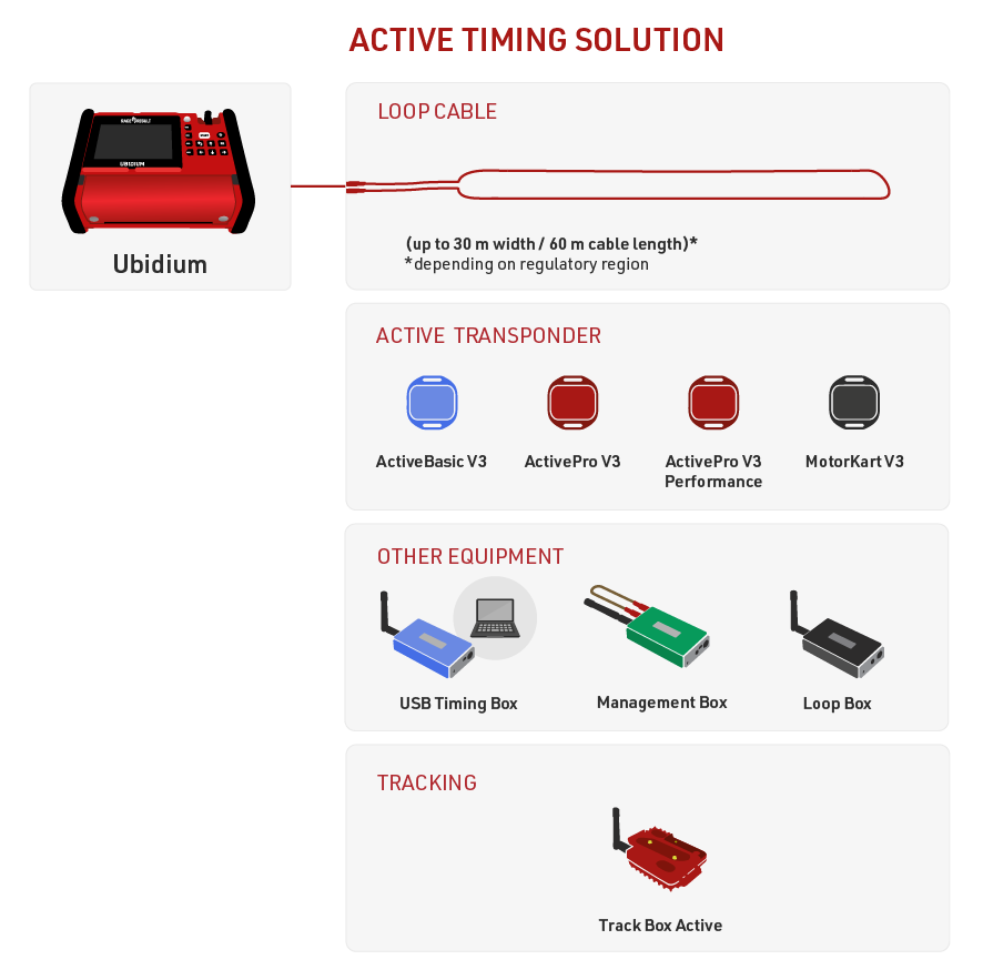
Active timing is possible with Ubidium, RACE RESULT Decoder with an Active Extension or using the standalone USB Timing Box.
The Loop Box provides additional flexibility to the setup, it can be run as a standalone timing point, but must be used with one of the main Active systems to receive the data either wirelessly via 2.4 GHz or from Store Mode on the transponder.
The Track Box Active uses 2.4 GHz to receive trackpings from transponders (when activated), and does not rely on any additional loop cable. Track Boxes contain a different algorithm for calculating times and so offer lower precision and should not be used in areas where participants may be stationary for prolonged periods of time (such as Triathlon transition zones).
USB Timing Box
The RACE RESULT USB Timing Box allows you to replace the Decoder and Active Extension with a single USB connection to your PC.
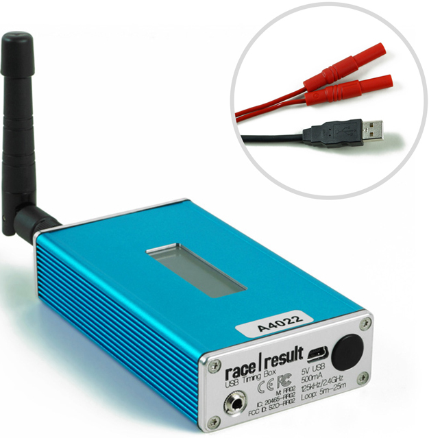
The USB Timing Box can be used time sporting events, scan tags at race pack pickup, or for just about any other application: the open-source software of the USB Timing Box allows you to develop any solution that may have nothing to do with sports timing.
The USB Timing Box is compatible with our Loop Box where the USB Timing Box can receive passings from a Loop Box in Repeat Mode. The USB Timing Box does not include additional functionality such as a 3G connection or GPS time synchronization.
Loop Box
The Loop Box is an additional stand-alone device which activates the active transponder, but does not process the data of the transponders. Instead, the passing data will either be repeated to another box or be stored in the transponder.
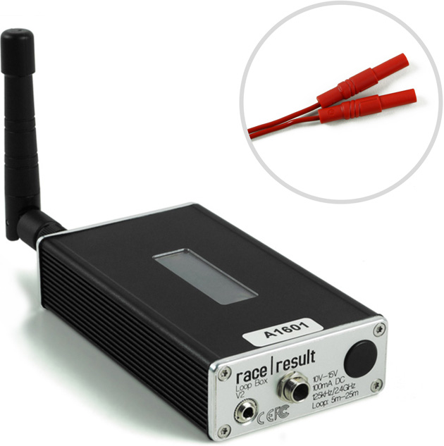
In this section, the USB Timing Box and Active Extension will be referred to as the main loop.
Active Extension
The Active Extension connects to the feature port of the RACE RESULT Decoder in order to operate as an active system.
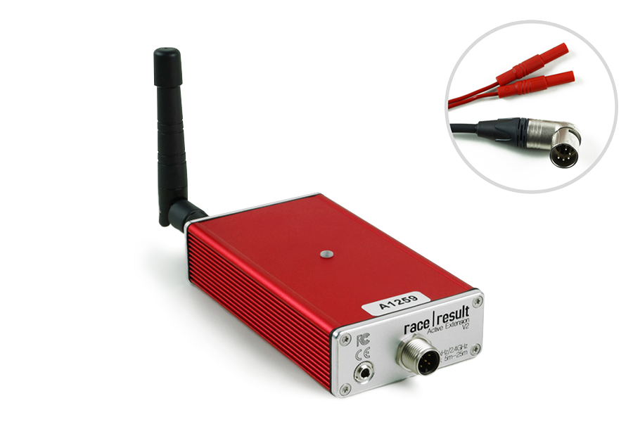
The Active Extension does not have a screen and it entirely controlled by the decoder. When in use the time base of the decoder is managed by the Active Extension which contains a more precise internal clock.
The Active Extension can be used with data cables up to 30m in length, allowing the decoder to be positioned further away from the timing point. It can also be used with the Loop Box to receive passings transmitted by repeat mode, or receive passings which were stored on the transponder.
Management Box
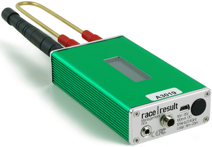
The Management Box is a key piece of equipment for efficiently managing your active transponders. It also allows you to place your ActivePro / MotorKart transponders into deep sleep mode which can save 40% of the energy used by the transponders.
The Management Box is also used to active tracking mode on ActivePro / MotorKart transponders when being used with Track Boxes.
Active Setup
The active system consists of 2 key elements that must both be set up correctly, the Loop Cable and the 2.4GHz antenna for receiving data.
Loop Cable Set up
In most cases, the cable loop will be laid on the ground and either taped down with duct tape or covered by a mat.
The loop cable should form a rectangle with a width of between 30cm and 60cm, with the exact line on which you wish to record a time positioned across the middle of the length of the loop.
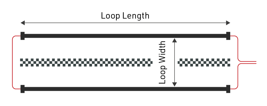
Where possible use a loop of exactly the required length, at all times avoid coiling any excess loop cable since this can cause interference resulting in transponders not being activated. Loop cables cannot be installed on metal surfaces, these will completely inhibit the loop signal meaning no passings will be generated.
Loops can be buried in the ground, particularly for motorsports or on soft surfaces, when doing so it is common practice to protect the loop using some sort of pipe.
Loop Width
If you require higher precision, the loop should be narrower, and greater care must be taken to set up the loop precisely. Note that 0.01 second means only 5cm distance at 70km/h. So aligning the loop a few centimeters askew will have a negative effect on precision.
A wider loop, on the other hand, will result in higher read height but may lower precision. This is usually the preferred setup since most sports requiring the greatest precision require a PhotoFinish camera for verification.
In general, you should only make your loop narrower if you are confident that all transponders will be mounted at the same height (below 100cm or 50cm for MotorKart) and the maximum speed is also below 100km/h, this should also then be complemented by a lower Loop Power to maximise precision.
You can see some guidelines for loop width / loop power and the resulting max detection height here
2.4GHz Antenna
The 2.4GHz antenna is used to communicate with the transponder, this is how the system receives the exact passing time from the transponder. It is critical that there is a clear line-of-sight between transponders and the 2.4GHz antenna, and the antenna must be used at all times.
In the event that the Active Extension has an obscured view of transponders then it may be necessary to use an Active Range Extender, this is a higher gain antenna, fitted to a longer cable allowing the antenna to be mounted higher and away from interference.
Note that the additional gain of the antenna is lost in the length of the cable and so simply setting up the range extender on the ground in the same position will have no additional benefit.
Antennas should be mounted pointing vertically upwards and kept away from metal as much as possible since this can interfere with the signal.
Active Settings
The following settings are applied to all Active timing devices, and are important to ensure reliable and accurate operation whilst timing.
Refer to the individual device guides to understand how to set the values on the corresponding device.
Active Detection Data
With each read the system saves some useful information about the passing, understanding this can help to better interpret your data and identify potential problems.
Since Active Transponders contain more onboard circuitry and communicate on the 2.4GHz channel they are able to store and send more information with each passing, understanding the Hits / RSSI values is also slightly different as explained below.
- Hits - The number of times the transponder has seen the loop pattern (which is repeated at 150 times per second), up to the strongest Loop Strength.
- RSSI (only useful for V2 Transponders and beyond, not applicable to Basic Transponders) - There are two radio links involved, 125kHz Loop and 2.4GHz Antenna for data communcation. We want to know the quality for both, which is why the system reports two values packed into one figure.
- X refers to the 2.4Ghz received signal strength where -90dBm is the weakest and -58dBm is the strongest signal
- Y refers to the Loop power where 1db is the weakest and 16db is the strongest.
- Loop - The Loop ID of the device which recorded the passing.
- Channel - The Channel ID of the device which recorded the passing.
- WUC - Wake-Up-Count of the transponder is the number of times the transponder has been activated by a loop.
- Batt - The battery voltage of the transponder, we recommend retiring transponders with < 2.2v.
- Temp - The internal temperature of the transponder.
- SFlag - Will be between 64 and 127, or greater than 192, if the passing was stored on the transponder or the V3 Transponder issued a warning.
| Guidelines for detection strength | Hits | 2.4GHz RSSI (X) | 125kHz Loop (Y) |
| Perfect (could not be better) | 20..60 | better than -75dBm (-58dBm best for passing) |
8dB...16dB |
| OK (nothing to worry about) | 10...20 | -80dBm...-70dBm | 6dB...10dB |
| Not Great (still working, but could be better) | 5...10 | -85dBm...-75dBm | 4dB...8dB |
| Barely Detected (setup should be checked) | 1...5 | -90dBm...-80dBm | 1db...4dB |
How to improve detection quality:
- 2.4GHz: Make sure the receiving antenna has a direct line of sight to the transponder. If this is not the case, try replacing the receiving antenna (elevating it) and/or use our Range Extender.
- 125kHz: Make sure there is a direct line of sight between the loop and the transponder. When mounting the transponder on metal/carbon, please use our Chip Holders to leave some space between the transponder and metal. Also check the loop width, loop power (detection height) and transponder placement.
Technical Specifications
Dimensions & Standards |
|
|---|---|
|
Regulatory Conformity and Standards |
EN60950 (safety) CE, RoHS, FCC |
| Operating Temperature | -30°C to 70°C |
| Dimensions | 27mm x 66mm x 117mm |
| Active Extension | |
|
Protection Class (with data cable / antenna connected) |
IP67 -waterproof- |
| Weight | 190g |
| USB Timing Box | |
|
Protection Class (with cable / antenna connected) |
IP52 - water resistant- IP54 with bumper usage |
| Weight | 266g |
| Loop Box | |
|
Protection Class (with cable / antenna connected) |
IP52 - water resistant- IP54 with bumper usage |
| Weight | 272g |
| Management Box | |
|
Protection Class (with cable / antenna connected) |
IP52 - water resistant- IP54 with bumper usage |
| Weight | 274g |
RF Characteristics |
|
|---|---|
|
2.4GHz Channel Frequencies - Main / Backup (Worldwide compliance) |
1: 2.480MHz / 2.410MHz 2: 2.405MHz / 2.470MHz 3: 2.425MHz / 2.465MHz 4: 2.475MHz / 2.440MHz 5: 2.415MHz / 2.445MHz 6: 2.460MHz / 2.430MHz 7: 2.435MHz / 2.455MHz 8: 2.450MHz / 2.420MHz |
| 2.4GHz TX Power |
17.5dBm |
|
Loop Frequency & Data |
125KHz Data packet = Loop ID + Channel Packet Rate: 150Hz OOK-modulation, Manchester encoded, 16-bit anti-false-wakeup pattern |
| Loop Power | 100% = 250mA RMS regulated peak current |
| Loop Cable & Length |
5m - 25m, >0,5mm² standard 4mm banana plugs |
Detections |
|
|---|---|
|
Max Read Range 25% Loop Power 100% Loop Power |
60cm (2ft) 2.5m (8ft) |
| Active Extension | |
|
Transponder Read Rate |
>100 transponders per second burst for 20 seconds >50 transponders per second continuously |
| Internal Data Buffer | 1,000 passings |
| Forewarn Data Delay | 100ms (from entering the loop center) |
| Max Passing Data Delay | 250ms (after loop center) |
| Repetitive Passing Rate Over Loop | 1 per second |
| Clock Stability |
24/1,000th second per day 0.28ppm TCXO calibrated to rubidium frequency standard traceable to NIST |
| USB Timing Box | |
|
Transponder Read Rate |
>100 transponders per second burst for 20 seconds >50 transponders per second continuously |
| Internal Data Buffer | 1,000 passings |
| Loop Box | |
| Transponder Read Rate* | up to 40 transponders per second continuously |
| Passing Transmission Delay | 200ms - compensated |
| Maximum Repeat Range | 900m with direct line of sight |
| Internal Data Buffer | 1,000 passings |
| Management Box | |
|
Transponder Read Rate |
>100 transponders per second burst for 20 seconds >50 transponders per second continuously |
| Internal Data Buffer | 1,000 passings |
*Reduced to account for passing transmission in Repeat mode
Battery & Connections |
|
|---|---|
| Active Extension | |
| Data Cable |
5m (standard) 15m, 30m (optional) |
| USB Timing Box | |
| Battery | 4000mAh, 3.7v Li-Po |
|
Battery Life (Standalone Unit) |
12h - 20h dependent on Loop Power |
| USB 1.1 | 500mA |
| Loop Box | |
|
Battery |
4000mAh, 3.7v Li-Po |
| Battery Life |
12h - 20h dependent on Loop Power |
| Battery Charging |
10v - 15v, 100mA (at 100% Loop Power) |
| AC Power Supply | 110v - 230v, 50 / 60Hz |
| Management Box | |
| Battery | 4000mAh, 3.7v Li-Po |
|
Battery Life (Standalone Unit) |
12h - 20h dependent on Loop Power |
| USB 1.1 | 500mA |
| Battery Charging |
10v - 15v, 100mA (at 100% Loop Power) |
| AC Power Supply |
110v - 230v, 50 / 60Hz |
Serial Port Connection (USB Timing Box & Management Box) |
|
|---|---|
| Bautrate | 19200 bps |
| Stop Bit | 1bit |
| Parity | OFF |
| Databits | 8bits |
| Softflow-Control | OFF |
| Hardflow-Control | OFF |
| DTR-Line | Special Purpose |
Active System FAQs
Track Boxes
Track Boxes offer the highest flexibility of any timing system, designed to offer a simple, portable setup for capturing additional splits on course. With more split data captured it becomes easier to offer live tracking visualisations and engaging leaderboards for spectators. Single-button operation means that anybody can setup a timing point, in a form factor which can easily be carried to remote timing points.

Due to their design Track Boxes are not intended for use on critical timing points such as Start or Finish lines, they are best suited to on-course splits which do not require such high accuracy.
Track Boxes are available in 2 versions
Active
The Active Track Box provides the easiest way to capture additional times for participants when using ActivePro V2 or MotorKart transponders. Active Track Boxes do not use a loop for activation of transponders but instead receive Track Pings from passing Transponders via the 2.4GHz channel to record the time of passing.
The small form factor, single-button operation, and built-in magnets of the active Track Box allow for the quickest race day setup of any system. With the additional GPS data recorded by Track Boxes more accurate tracking visualisations can also be produced.
Transponder Track Ping activation and Track Box Management can only be done using the Management Box
Passive
The Track Box Passive provides a simple solution for split points for events that are timed using the RACE RESULT passive transponder. The Track Box is an all-in-one solution with the reader, battery, and antenna integrated into a single unit which can be easily transported and set up faster than a conventional decoder and antenna.
The Track Box Passive includes an integrated stand and magnets which allow for a variety of mounting methods and angles.
As the Track Box includes a 2.4GHz module it can also operate as an Active Track Box simultaneously to receive Active Trackpings, using the same setup principals as the Active Track Box.
Track Box Configuration
Track Box Setup
Due to the nature of how Track Boxes work compared to a conventional timing system, some additional precautions and care should be taken in order to maximize read rates of Track Boxes.
LED Blink Codes, Button & Beeper
LED Blink Codes
The Track Box has 2 LEDs on the front, the left is red/green and the right is blue, each LED indicates a different function
Red/Green LED
|
|
(Continuous red/green) - Less than 20s (directly after turning on) -> Firmware upgrade in progress |
|
|
(Continuous red) SIM Card error / Battery Under Voltage |
|
|
(Single red) no GPS, Network OK |
|
|
(Single red, double red) no GPS, no network |
|
.................... |
(Double red) GPS OK, no network |
|
|
(Single red, triple red) no GPS, network OK Receiving active Track Pings! |
|
|
(Single red, double red, triple red) no GPS, no network Receiving active Track Pings! |
|
|
(Single green) GPS and network OK |
|
|
(Single green, triple green) GPS and network OK Receiving active Track Pings! |
Charging:
 Battery full
 Battery not yet full
Note: the Track Boxes are always on when charging.
Blue LED (Passive Only)
 |
On (Solid) - Passive reader active On (Flashing Rapidly) - Passive reader active and detecting transponders Off - Passive reader switched off |
Note: See Orientation of Track Boxes to understand the conditions in which the passive reader will be switched off
Button
Press the button to switch the Track Box on.
Keep the button pressed for 1 second to turn off. If the Track Boxes are stacked, or very close to each other, they will send a shutdown command via 2.4GHz to shut down all boxes in the stack.
You can reset the Track Box by pressing the button for 10 seconds.
If the Track Box is locked via Tracking Box Configuration Rules, the LED will not blink at all and the button won't turn off the box. You can still reset the box by pressing the button for 10 seconds.
Beeper (Passive Only)
The internal beeper will signal a passing similar to the decoder beep. While the decoder beeps as soon as a transponder is in range, the Track Box Passive beeps when the actual passing has been created.
When you hear a continuous beep and see the box blinking red/green, it signals a fatal error (see above).
How Track Boxes Work
Below is some key information about how the Track Boxes work to help maximise the performance of the device.
Technical Specifications
Track Box FAQs
RACE RESULT Decoder
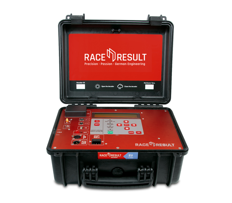
The RACE RESULT Decoder receives the signals from the transponders using antennas, then calculates and saves the final detection time, based on a very precise clock and the transponders’ signal strength when crossing the timing line.
It provides these passings (bib number, time, and additional information) to the scoring software such as RACE RESULT 12 or uploads the data directly to an Internet server.
The decoder does not perform further calculations such as calculating the net time, lap times, etc. All this will be done by your scoring software.
It also guarantees uninterrupted operation as it runs independently from a computer and external power supply. All passings information is automatically stored on the device.
Safety and Regulations
General Safety Responsibilities
This unit has been designed and tested in accordance with the CE Certificate of Conformity and has left the manufacturer's plant in condition, fully complying with safety standards.
To maintain this condition and to ensure safe operation, the user must observe all instructions and warnings given in this operating manual.
Applicable local and national safety regulations and rules for the prevention of accidents must be observed in all work performed.
FCC/IC Statement
Changes or modifications not expressly approved by the party responsible for compliance could void the user's authority to operate the equipment.
This device complies with Part 15 of the FCC Rules and with Industry Canada license-exempt RSS standard(s). Operation is subject to the following two conditions: (1) this device may not cause harmful interference, and (2) this device must accept any interference received, including interference that may cause undesired operation.
Le présent appareil est conforme aux CNR d'Industrie Canada applicables aux appareils radio exempts de licence. L'exploitation est autorisée aux deux conditions suivantes : (1) l'appareil ne doit pas produire de brouillage, et (2) l'utilisateur de l'appareil doit accepter tout brouillage radioélectrique subi, même si le brouillage est susceptible d'en compromettre le fonctionnement.
Warnings and Cautions
The following alerts are used in this manual:
- WARNINGS alert users of potentially dangerous situations.
- CAUTIONS alert users of potential equipment damage.
Warnings and cautions are indicated by:
- the text WARNING or CAUTION,
- a description explaining the hazard and how to avoid it,
- an icon:

Where to Operate the System
UHF operates globally on different frequencies (e.g. Europe 865 - 868 MHz, USA 902-968 MHz, AUS 920-925 MHz) with different detailed regulatory requirements. That is why RACE RESULT provides different versions of the system for different regulatory areas. When operating the passive part of the system in another country, make sure it complies with local regulation.
The RACE RESULT Active System uses universal frequencies that can be used globally.
Decoder Elements
Data Connections
The timing data (“detections” or “passings”) can be retrieved in four different ways:
- via the Ethernet interface
- via the USB port
- When uploading the data through the internal 2G/3G/4G module, the data can be downloaded from the Internet.
- By accessing the decoder through your browser
Test Mode and Timing Mode
After booting, the decoder is in Test Mode, i.e. it does not store any detections. Instead, it steadily beeps/blinks when seeing a transponder. This way:
- The setup of the system can be checked easily to make sure it detects as expected.
- You do not need to filter any detections in the scoring software from athletes' warm-up before the race.
Timing Mode
The Timing Mode will be started when pressing the START button on the key pad. If not running on day time/GPS time, the time will start from 0:00:00 and the decoder will immediately start processing and recording every tag passing the antenna.
Stopping Timing Mode
The Timing Mode can be stopped by pressing the Cancel button or by selecting the entry Stop Timing in the menu. The system will then be back in Test Mode.
Next time the Timing Mode is started, the system creates a new file for the detections, indicated by a new file number on the main screen. Note that:
- Through the Ethernet interface, only detections from the current file can be read.
- All (old) files can be accessed any time through the browser or USB stick (see Data Connections).
Emergency File
If you forget to start Timing Mode, you can still access an emergency passings file through the Browser Access.
Time Setup
While in Test Mode the time of the decoder can be set via the Time menu. The following options are available:
Set Running Time
The time entered will be set and start running even while being in Test Mode. This option is usually used to set the clock time / time of day.
Set Start Time
The time entered will be set, but will not start running before starting the Timing Mode. This option is usually used to set the time to 0:00:00.
Set GPS Time
When using this option the system will try to receive the precise time from a GPS satellite. It may be that the GPS signal cannot be received inside buildings and under trees. In this case the system will show an error message after 60 seconds.
Configure GPS Time
Within the configuration you can set the time zone the decoder should use and adjust the value for Leap Seconds (this is normally only required when working with third-party hardware which does not correct for Leap Seconds).
Detection Setup
Active Extension Settings
| C | h | a | n | n | e | l | : | 7 | |||||||||||||||||||||||||||||||
| P | o | w | e | r | : | 0 | 4 | 0 | % | | | . | . | . | . | . | . | . | . | . | . | . | . | . | . | . | . | . | . | . | . | . | . | | | ||||||
| L | o | o | p | I | D | : | 1 | ( | B | a | s | e | ) | ||||||||||||||||||||||||||
| D | i | s | c | a | r | d | s | t | o | r | e | d | d | e | t | e | c | t | i | o | n | s | : | N | O |
Channel
For the Active Extension, by default the Channel ID is set to auto. In this case, the system performs a channel survey when turned on and selects the channel used the least in order to avoid interferences between the active system and other devices. Note that
- Even if a channel is heavily used by Wi-Fi, there would still be sufficient gaps to operate the active system on the same channel.
- Auto mode will usually select channel 1 because this channel is not used by Wi-Fi and is often completely free.
If necessary, a different channel can be selected, when selecting the channel setting the system will first perform a channel survey and then show the channels and their qualities. You should select the channel(s) with the highest percentage, this is the clearest channel and will have the least interference.
| C | h | a | n | n | e | l | s | ( | Q | u | a | l | i | t | y | ) | |||||||||||||||||||||||
| A | l | w | a | y | s | s | e | l | e | c | t | c | h | a | n | n | e | l | a | u | t | o | m | a | t | i | c | a | l | l | y | ||||||||
| 1 | ( | 3 | 2 | % | ) | 2 | ( | 3 | 6 | % | ) | 3 | ( | 0 | % | ) | 4 | ( | 0 | % | ) | ||||||||||||||||||
| 5 | ( | 5 | 0 | % | ) | 6 | ( | 1 | 0 | % | ) | 7 | ( | 6 | 5 | % | ) | 8 | ( | 6 | 1 | % | ) |
Power
Adjust Loop Power using the left and right arrow keys, to understand how Loop Power impacts performance see Loop Power.
Note that the Active Extension automatically determines the length of the loop and adapts the real power on the loop accordingly, so that the same percentage value should always result in roughly the same read height.
Loop ID
Similar to the channel, the Loop ID normally runs in an auto mode. The RACE RESULT Active Extension, USB Timing Box, and Loop Box, each send out a status beacon every second on their Repeat channel. When turning on an Active Extension with auto loop mode, it will listen a few seconds for the signals from the other Active devices and then select an unused Loop ID.
The auto loop mode is easy to use, but it may be easier to assign fixed Loop IDs so that you immediately know which Loop ID belongs to which device. Make sure not to assign a Loop ID twice - otherwise you will receive the detections on both Active devices (when running on the same channel).
If you accidently select a Loop ID which is already being used, the Loop ID will flash between the occupied Loop ID and an X. The example below shows a RACE RESULT System with a Loop ID which has already been selected. Another Active device has been assigned this Loop ID, so it should not be used.
| C | o | u | n | t | : | 3 | 8 | 2 | 3 | T | i | m | e | : | 1 | 1 | : | 4 | 0 | : | 2 | 3 | . | 3 | 2 | 3 | z | z | z | z | z | 0 | 1 | ||||||
| F | i | l | e | N | o | : | 2 | 9 | 8 | I | P | : | 1 | 9 | 2 | . | 1 | 6 | 8 | . | 1 | . | 2 | 0 | 2 | z | z | z | z | z | 0 | 1 | |||||||
| U | p | l | o | a | d | : | o | f | f | C | h | # | : | 1 | L | o | o | p | # | : | X | 5 | 0 | % | z | z | z | z | z | 0 | 1 | ||||||||
| U | S | B | : | n | / | a | B | a | t | t | e | r | y | : | █ | █ | █ | █ | █ | █ | █ | █ | z | z | z | z | z | 0 | 1 |
V1 Legacy Mode
By default the V1 Legacy Mode is set to AUTO, in this mode it will use both the primary and backup channels to receive passing data, however if a transponder is detected which does not support this then the switching will be disabled until the system is rebooted or the setting is modified manually.
Channel switching can be set to ON to always keep it on, or OFF to always disable it, however this is not recommended since forgetting to change the setting back could have a negative impact on the data transmission.
Feature Port
The feature port serves to connect any type of accessories to the RACE RESULT System. It provides ground, +12V, +5V, RX and TX. Besides the Active Extension (see Active Loop Setup) there are several Accessories you can connect.
The pins on the feature port are used as follows:
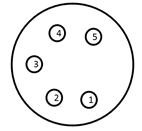
1: +4,8V output (5V - Shottky diode) (500mA max)
2: +11V-15V (unfused! two way!)
3: TXD 3,3V TTL
4: RXD 3,3V TTL internal Pull Up 10k
5: IO Digital Trigger - max 3,3V
SHIELD = GND
 Connect non RACE RESULT equipment at your own risk!
 Short circuits will damage the system.
 Only use original Neutrik connectors, cheap connectors do not connect GND reliably.
External Battery Port
The internal battery of the RACE RESULT System lasts for approximately 6-8 hours (passive ground antenna), or 24 hours (active loop). The external battery port can be used to connect a larger battery or a car (via the cigarette lighter) for longer uptimes without another power supply.
When determining the necessary size of a battery, calculate with a power consumption of 2 A using the passive antenna and 500mA using the active loop.
The system is sold with a special cable with XLR connector for the decoder on one end and a car connector on the other end. The pins are used as follows:
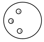
1: GND
2: +12V Input (10A Fuse)
3: NC
SHIELD = GND
Note that the external battery does not charge the internal battery, but instead power will be taken from both batteries, internal and external, at the same time.
You can use the Battery Booster to discharge the external battery first.
Startup Options
In the System menu the Startup option can be set to the following values:
| do nothing | Do nothing after normal startup. |
| set GPS time | Set GPS time after decoder has booted. |
| GPS time & activate | Set GPS time and activate operation mode after decoder has booted. |
| GPS time, activate & upload | Set GPS time, activate operation mode and upload (with current settings) after decoder has booted. |
| GPS time & upload | Set GPS time and start upload (with current settings) after decoder has booted. |
Trigger Impulse / Marker
When pressing the START button again in Timing Mode, an additional marker will be created. A marker is a fake detection with a certain bib number which can be used in the scoring software, e.g. to indicate the start of a second start wave.
To enable markers open the Trigger Impulse settings from the Menu, the Timing mode should be set to "default (+marker)".
Warning: Changing this without understanding the other modes will result in lost timing data. See Alternative Timing Modes.
Changing the Marker will cycle between 'off', the marker number which can be edited and the option to create a new file instead of a marker. It is good practice to ensure that the marker number does not overlap with your bib number ranges, this can be set to any value up to 999999. There also is an option to increase this number every time a marker has been created.
Markers can be set using accessories for the Feature Port or 3.5mm input of the Active Extension or Loop Boxes. To use the active extension input then ensure to change the I/O setting, on the second page of the Active Extension menu, to "Trigger In".
If using external inputs such as photocells or start gates you may wish to set the External Start setting to "yes". With this enabled the sensitivity of the trigger is increased to ensure all triggers are captured. When set to no the trigger pin is rechecked after a short delay (50ms) to prevent false triggers, but with high speed events this could result in missed triggers.
In RACE RESULT 12 markers are automatically identified and listed in the Start Times / Finish Time Limits menu, markers are stored internally with a bib according to the marker number set on the decoder.
Caution: If a marker number matches the bib of a participant in the event file then the marker will be assigned to the participant.
Online Firmware Update
There are frequent firmware updates, e.g. for new features or new accessories. It is recommended to update the firmware frequently. See Firmware Release Notes.
Proceed as follows to update the firmware of your decoder:
- Make sure, the system is connected to external power, so that it does not run out of battery during the update process.
- Connect the decoder to the internet via ethernet cable, we recommend connecting directly to your internet router.
- Make sure DHCP is used or make sure the standard gateway and DNS server are set correctly (see Ethernet Connection).
- Go to the main menu, select the entry System, select Check online for new firmware and press the OK button. The system will now do the update process and then restart.
A standard firmware update requires around 15 MB of data, or up to 25 MB if it also contains an update of the UHF reader's firmware.
Recommendation: we don't suggest running the decoder's FW update over mobile connection, as it may not always be successful.
Decoder Configuration File
You can export a configuration file from one decoder, modify it and upload it to another decoder. This makes it much easier to configure all of your decoders the same way. This also gives you the ability to configure a decoder from your computer with a text file.
Downloading the Configuration File
As of firmware version 2.55 the decoder configuration file is copied automatically when a USB drive is plugged in to the decoder, the same way in which passings files are also copied. The file by default will use the decoder ID and is saved as a .toml file which is a standard type for configuration files.
On the System Menu there is an option to determine whether the exported configuration file will contain passwords or not, this is set to no by default. If enabled then passwords will be stored as plain text in the file.
Modifying the Config File
You can edit a decoder configuration file in any text application.
When changing a setting only apply values that are available within the decoder. For example, the On Detection setting has only three modes; BEEP, BLINK or BEEP and BLINK. You can not create a new mode where both BEEP and BLINK are false.
The available options for the configuration file are outlined below.
To avoid overwriting the original configuration file, always make sure to save your custom file with a new file name and set a new title. Files will be displayed on your decoder by their title name within the configuration file, not their filename.
Applying a new Config File
To upload a decoder configuration file you need to place the file on a flash drive within the raceresult folder, it is easiest to use a USB drive which already contains the automatically copied file directory.
e.g. raceresult>D-5662>MyCustomConfig.toml
Once you have added your configuration files to your USB drive, plug the USB drive into your decoder. You will be asked if you want to view the available configuration files.
| C | o | n | f | i | g | u | r | a | t | i | o | n | f | i | l | e | s | f | o | u | n | d | . | S | h | o | w | l | i | s | t | ? | |||||||
| D | o | n | o | t | u | n | p | l | u | g | d | r | i | v | e | w | h | i | l | e | f | l | a | s | h | i | n | g | ! | ||||||||||
| > | n | o | < | ||||||||||||||||||||||||||||||||||||
| y | e | s |
If you do not want to upload a new configuration you can press no, otherwise select yes to view the available files.
| C | h | o | o | s | e | a | c | o | n | f | i | g | f | i | l | e | . | ||||||||||||||||||||||
| P | r | e | s | s | C | a | n | c | e | l | t | o | a | b | o | r | t | . | |||||||||||||||||||||
| D | - | 5 | 6 | 6 | 2 | S | a | m | p | l | e | 1 | |||||||||||||||||||||||||||
| > | O | K | < |
If more than one configuration file is present on the USB drive then you can scroll left/right to select the file you want to upload and then press OK. All of the settings in the file will be used to update your decoder settings.
Passive Detection Data
With each read the system saves some useful information about the passing, understanding this can help to better interpret your data and identify potential problems.
As well as the basic information including the Time and Decoder ID, the following data is recorded for a passive read:
- OrderID - The ID number of the order for which the transponder was printed.
- Hits - The number of times the chip was seen by the decoder during the passing (Not applicable to Track Box Passive data, you should expect lower hits due to the transponder communication protocols).
- RSSI - The strength of the signal received (in dBm) from the passing when the read was recorded.
- A higher value is a stronger detection. For example -42 is better than -60. The best possible value is -35 and the worst value is -85dBm, this is the sensitivity limit.
- Typical values are in the range of -50dBm..-70dBm.
- The RSSI value is the value of the best hit according to your decoder's detection mode.
| Guidelines for detection strength | Hits | RSSI |
| Perfect (could not be better) | 75...255 | -35...-55 |
| OK (nothing to worry about) | 20...75 | -55...-65 |
| Not Great (still working, but could be better) | 5...20 | -65...-75 |
| Barely Detected (setup should be checked) | 1...10 | -70...-85 |
| Transponder is in range but not moving* | high value | low value |
*Such as a participant who has already finished watching the race near the finish line whilst still wearing their transponder.
Technical Specification
Safety & Conformity |
|
|---|---|
|
Protection Class (Lid Closed) |
IP54 -water resistant- |
| Regulatory Conformity and Standards | EN60950 (safety) CE, RoHS, FCC |
| Relative Humidity |
maximum 90% non-condensing |
| Temperature Range | -20°C to 50°C |
| Dimensions / Weight |
36cm x 26cm x 45cm 12.5kg |
Power & Battery |
|
|---|---|
|
AC Power Supply |
110V - 230V, 50/60Hz 2A fuse |
| DC Power Supply |
12V - 14V 2A (when battery full) |
| Battery Flight Safety |
15Ah (Pb) IATA - A48 / A67 |
| Charging Time |
4h (switched off) 7h (running) |
| Power Consumption |
26W (battery full) 60W (battery charging) |
| Battery Life (Passive) | 8h - 10h [1] |
| Batter Life (Active) | 24h [1] |
[1] Battery life can be reduced by usage of LTE/4G (-10 %), low temperature (-25 % @ 0°C/32°F) and battery age
Connectivity |
|
|---|---|
|
29 Band 4G / LTE / 3G / 2G Module (Worldwide Coverage) |
FDD: B1 / B2 / B3 / B4 / B5 / B7 / B8 / B12 / B13 / B18 / B19 / B20 / B26 / B28 TDD:B38 / B39 / B40/ B41 WCDMA: B1 / B2 / B4/ B5 / B8 / B6 / B19 GSM: B2 / B3 / B5 / B8 |
| Antenna |
Internal External SMA (optional) |
| SIM Card |
2FF standard |
| Charging Time |
4h (switched off) 7h (running) |
Ports & Features |
|
|---|---|
|
Internal GPS |
uBlox 50 channel receiver, 30 seconds cold start |
| 2 x LAN |
dual 100MB / 10MB LAN port auto crossover detection switched internally for loop through to next device |
| USB |
storage drive for backup Wi-Fi adapter (optional) |
| Antenna Ports |
8 x BNC |
| Feature Port |
supplies 5v (500mA), 12v (500mA) output, start gun / photo sensor input |
| Audio Beep | 3.5mm headphone plug (mono) |
RACE RESULT Decoder FAQs
Passive Antennas
The passive UHF antenna cables connect to the antenna ports on the back of the decoder and are used to detect the RACE RESULT passive transponders/tags. Compared to the active transponders, the passive tags are far less expensive but have less precision and need to be attached (to the race bib, or to an athlete’s ankle, shoe or bicycle) in a certain way for reliable detection.
Antenna Types
RACE RESULT offers two types of antennas for use with passive tags: the ground antenna, used for almost any type of race (running, triathlon, mountain bike, etc.) or the side antennas (available in high gain linear or circular polarizations), which can be used for a flat finish line to avoid the slightly raised profile of the ground antenna or for special applications such as canoe races, skateboard races, etc. Note that the side antennas have two major disadvantages:
- When several athletes pass the timing line they may block the signal from the antenna as the signal does not go through the human body. In other words, the side antenna should only be used for low-density split timing points.
- Since the antenna field is horizontal and does not have a defined end, tags close to the timing line can be detected easily. That is why the side antennas are not recommended for finish line scenarios when athletes can stand close to the system.
As a consequence, the ground antenna is always recommended use where possible and side antennas should only be used when necessary.
Note: side antennas may not be available for sale in all regions.
Folding Ground Antenna (5000 series)
RACE RESULT's patented folding ground antenna is the recommended setup for most applications, in particular mass participation running events.

The standard 4.8m ground antenna is comprised of 8 segments of 60cm each, with each element containing an antenna, additional extension kits are available for 6m, or up to 8.4m maximum connected to a single decoder.
By using a ground antenna the distance between antenna and transponder is reduced for all positions and the risk of obstruction between antenna and transponder is also reduced.
High Gain UHF Antenna for Special Applications
The High Gain UHF Antenna is designed for special applications where a ground antenna may not be suitable or possible to use. We always recommend using our Ground Antenna where possible, since all antennas require line of sight between the antenna and transponder.
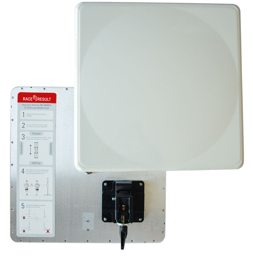
Using the included clamp and mount, antennas can be attached to a variety of structures and easily rotated to match the required orientation of antenna to the transponder. The antenna is linearly polarized but can work with either vertically or horizontally orientated transponders, to do so you must ensure that the antenna is correctly orientated to ensure optimal read rates.
To ensure the antenna is correctly orientated the label on the back acts as a guide, the transponder pictured on the label should match the orientation of the transponders which you will be reading, there is also text to help ensure that this can be communicated.
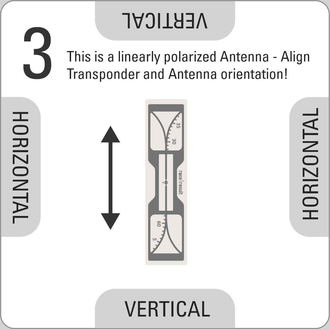
To rotate the antenna press the silver quick release pin on the clamp, remove the antenna from the clamp and rotate accordingly then push the brass knuckle back in to the clamp, aligning the clamp with the guide on the antenna.
Setup Guidelines
- When setting up antennas facing each other they must be connected to the same decoder, do not use different decoders when antennas are facing each other.
- For optimal precision we recommend a setup with 2 antennas on each side, mounted one above the other, with both pairs facing each other, and all four antennas connected to the same decoder using 12m cables for the antennas positioned further away from the decoder.
- When using main and backup systems the minimum gap between each setup should be equal to the width of the timing point. A chip in the middle of the 2 should not be detected by either system to ensure there is no conflict between antennas.
- When using main and backup systems the decoders should be positioned on opposite sides of the course (e.g., main decoder on the left of the course, and backup decoder on the right of the course), this ensures maximum detection strength on each side.
- For maximum read rate you can offset antennas on the same side slightly (e.g. 80° and 100° to the road), this maximises the width of the read field.
- When using multiple antennas with a large gap between them, you need to consider the decoder's Detection Setup settings to ensure optimal accuracy. If a transponder travels at high speed and passes both antennas within the reaction time then the time may be taken from the later antenna if the RSSI is stronger. This can be avoided by reducing the reaction time or using multiple decoders spaced apart sufficiently.
Warning: As this is a 13dBi High Gain antenna you will need to set your decoder power accordingly to comply with local regulations.
Connecting Antennas to the Decoder
For maximum performance the antennas need to be connected before turning on the decoder since it performs a fine tuning while booting. When connecting the antennas after turning on the decoder, the system still works but the performance may be slightly reduced.
Antenna Indicator on the Display
The display will show a block (█ - or A/B if one of these frequencies has been selected, see above) for an antenna port if an antenna is connected, or an X if no antenna is connected or if the antenna is broken:
| N | o | P | a | s | s | i | n | g | s | T | i | m | e | : | 0 | 0 | : | 0 | 0 | : | 0 | 0 | . | 0 | 0 | 0 | 4 | 5 | 6 | 2 | |||||||||
| F | i | l | e | N | o | : | 0 | I | P | : | 1 | 9 | 2 | . | 1 | 6 | 8 | . | 1 | . | 2 | 0 | 0 | 2 | 5 | 2 | 3 | 3 | |||||||||||
| U | p | l | o | a | d | : | o | f | f | A | n | t | e | n | n | a | s | : | █ | X | █ | █ | █ | █ | █ | █ | 2 | 6 | 6 | ||||||||||
| U | S | B | : | n | / | a | B | a | t | t | e | r | y | : | █ | █ | █ | █ | █ | █ | █ | █ | 2 | 1 | 1 | 1 |
The left-to-right order of the antenna indicators mirrors the left-to-right order of the ports on the back (or right-to-left when looking from the rear).
When an antenna detects a tag, the symbol will switch to an O for the duration of one second.
| N | o | P | a | s | s | i | n | g | s | T | i | m | e | : | 0 | 0 | : | 0 | 0 | : | 0 | 0 | . | 0 | 0 | 0 | 4 | 5 | 6 | 2 | |||||||||
| F | i | l | e | N | o | : | 0 | I | P | : | 1 | 9 | 2 | . | 1 | 6 | 8 | . | 1 | . | 2 | 0 | 0 | 2 | 5 | 2 | 3 | 3 | |||||||||||
| U | p | l | o | a | d | : | o | f | f | A | n | t | e | n | n | a | s | : | █ | █ | 0 | █ | 0 | 0 | █ | █ | 2 | 6 | 6 | ||||||||||
| U | S | B | : | n | / | a | B | a | t | t | e | r | y | : | █ | █ | █ | █ | █ | █ | █ | █ | 2 | 1 | 1 | 1 |
In Europe, UHF has a very small bandwidth, which means two or more systems at one timing point can interfere with each other. When using several European RACE RESULT Systems at the same timing point, different frequencies should be set in order to reduce interferences. In the Frequency menu, you can chose between an Auto mode, frequency A and frequency B. Please see recommended frequency settings in the graphics below.
Frequency Setup (EU Systems Only)

Passive Antenna FAQs
Transponders
Transponders Overview
Passive Transponders:
 |
Bib with Transponder |
Details |
 |
Transponder on Roll |
Details |
 |
MTB Plate with Transponder | Details |
 |
Triathlon Transponder (disposable) | Details |
 |
Seatpost Sticker with Transponder | Details |
 |
HuTag | Details |
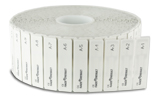 |
A-Z Transponder | Details |
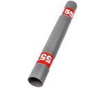 |
Baton | Details |
Active Transponders:
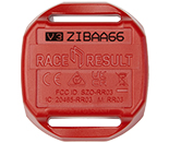 |
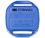
ActivePro |
Details |
 |
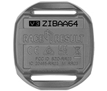
ActiveBasic |
Details |
 |
MotorKart | Details |
Passive Transponders
Active Transponders
Read these Specifications to find out the differences between the different active transponders.
Accessories
Test Transponder
The Test Transponder is the ideal tool to identify faulty passive antenna elements. It is designed to detect in 1m height with a narrow variance between detecting and not detecting. Only this enables you to do a true assessment of the cable and antenna quality. Bib Transponders detect mugh higher and are not a proper tool for testing the antenna performance!
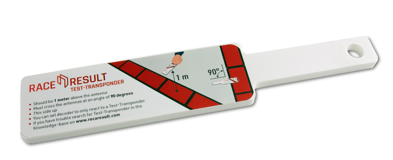
How to use the Test Transponder
- Make sure the decoder is in Test Mode, with the following settings activated.
-
Dead Time: 5000 ms Reaction Time: 0850 ms On detection: BEEP and BLINK ► Test Mode: Test transponder only ◄ - Hold the Test Transponder stickered side up directly over the center of the antenna, at 1 m height.
- The Test Transponder should start reading at around 1 Meter height, and if you lower it, definitely before 75 cm height.
If the Test Transponder does not read, review the following requirements, and repeat steps 1-3:
- Check the cable connection to the decoder
- Make sure only unfolded elements are connected to the decoder.
- Open the mat, check the connection to the antenna and look for potential damage at both the antenna and the cable.
- Make sure the antenna lid lies correctly on top of the antenna. It needs to have contact to the antenna itself.
- Check for water/moisture inside the antenna and clear it, if applicable.
- Remove anything covering the antenna mat (carpet, ice, etc.).
- Is there overhead metal (e.g. finish gantry truss)? If so, try moving the antenna a bit.
- Is there another decoder close by? Make sure they are not too close and/or running on different frequencies.
- Is there any other equipment on the same frequency (e.g. microphones)?
- Does the decoder report any errors? Please refer to the error codes.
- Check another decoder and antenna.
- If the problem occurs with the same antenna at a different decoder, most likely the antenna is faulty.
- If the problem occurs with a different antenna at the same decoder, most likely the reader (decoder) is faulty.
Active Range Extender
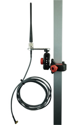
The Active Range Extender is used to increase the range for the 2.4 GHz signal on the Active System.
It can be used to have a better connection to the transponders or between boxes when using Loop Boxes.
WARNING: You cannot interchange the 2.4Ghz Range Extender and 4G/LTE External Antenna, the antennas are tuned to different frequencies and will not work in any unintended applications. The 4G/LTE External antenna is labelled with a red sticker at its base.
Just connect the SMA-connector to the Antenna port of the Active Box and place the Antenna on a high vantage point using the included clamp.
This is especially helpful on motor raceways, where it often is not possible to place a Box right on the track.
Start/Marker Push Button
The Start/Marker Push Button is an extended START button that will be connected to the Feature Port of the RACE RESULT Decoder. Instead of the button on the keypad, the button at the end of the cable can be pressed to start the Timing Mode or to set markers.
For events with many starts or single start it may be easier to push the button instead of pressing the keypad button on the decoder on the ground.
The Start/Marker Push Button is available as accessory in the raceresult.com shop.
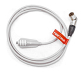
Light Barrier Cable
Using the Light Barrier Cable (available in the raceresult.com shop) an ALGE or Tag Heuer light barrier can be connected to the Feature Port of the RACE RESULT Decoder.
If only one athlete can cross the timing line at a time, the light barrier will be used to keep the time and the transponder will be used for the identification.
The light barrier can be positioned either before or after the detection line. The mode can be defined in the Feature Port menu.
When using one of these modes, the large LED of the system will light while the first but not the second information has been received.
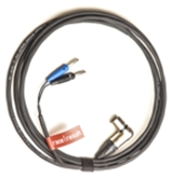
Battery Booster
The Battery Booster is used to increase the used capacity and prevent complete discharge of external batteries for the RACE RESULT Decoder.
It boosts the voltage feeded into the decoder, so that the external battery is always preferred over the internal.
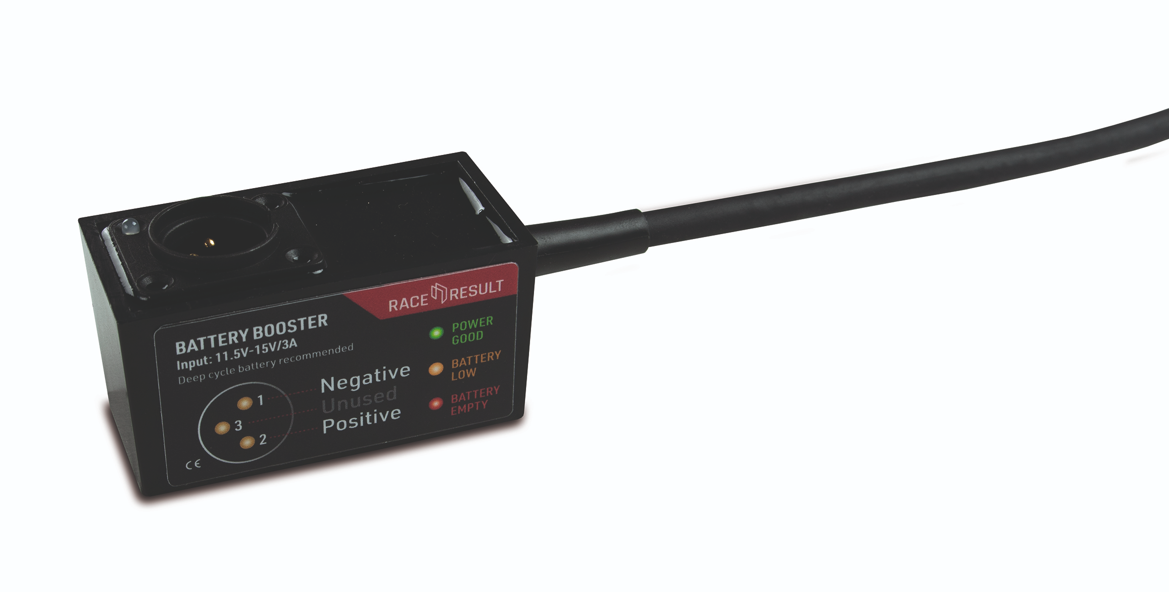
Insert the Booster between the 12V Jack of the decoder and the cable to the battery.
There is no switch, it immediately starts its operation, indicating the current state with its LED.
- When connecting a new external battery to the Booster, it must be charged to at least
- 11.9V to light the LED green
- 11.5V to light the LED orange
- else the booster will not turn on and light the LED red
- As soon as the Booster started successfully (as in "not red")
- a green LED indicates that the battery is still charged >10.9V
- an orange LED indicates that the battery is still charged somewhere below 10.9V
- when the LED turns red, the battery is discharged to below 10.5V and the output is disabled to protect the battery from deep discharge

Bumper for Loop Box & Management Box
The bumper for the Loop & Management Boxes provides extra protection against the ingress of water into the ports when the boxes are used in battery mode, as well as providing some extra protection against bumps and scratches.
To ensure the optimal weather resistance it is important to slide the bumpers fully onto the box. The seal to hold water out is located at the very base of the bumper; it is important that this part is snugly fitted on to the Box.
We do not recommend mounting the boxes upright when using the bumper, as water may collect in the gap between bumper and case, thus increasing the likelihood of water leaking inside the bumper.
USB Wi-Fi Adapter
From firmware revision 2.37 support for USB Wi-Fi adapters has been included for decoders which are using the latest compute board inside. This can be checked in the menu as explained below.
Currently the firmware only supports the following adapters:
- Edimax AC600
- Netgear A6100 (AC600)
Other adapters with the same chipset onboard may work but no support will be given for these, the Edimax AC600 has 4 variations; EU, US, AU and RU for regulation conformity.
RACE RESULT does not sell the USB Wi-Fi adapter directly, they are easy to locate through a number of online retailers.
System Care / Maintenance
It is important to maintain your timing equipment to ensure it stays in working order through an entire timing season. Here are some general guidelines for regular and annual maintenance.
Decoder
Regular Maintenance
- Check for firmware updates monthly.
- Keep your decoder clean. You can use a rag with a light cleaning fluid to gently wash off the faceplate of the decoder as well as the outside of the case. NEVER spray cleaning solutions directly on the decoder. First, spray the rag, then use the rag to wipe surfaces.
- You can use an air compressor or a can of compressed air to gently clean out the various ports on the decoder faceplate.
- Make sure there is no debris in any of the ports, specifically the Ethernet ports. These are large enough to catch small debris which can cause connection issues. If you see any, a q-tip soaked in rubbing alcohol can be used to clear the debris and clean the port. Be very gentle when doing this so as to not bend any of the internal pins.
- Look for any damage to the decoder. On occasion, the BNC connectors on the back can get smashed and no longer allow for an antenna to be connected.
Annual Maintenance
- Run a battery test to make sure your decoder's battery can last the recommended time.
- Check our online shop to see if your decoder qualifies for any of our update offers.
- Install the latest firmware update, especially if the decoder has been sitting for several months with no use.
- Check the various functions of your decoder.
- Check all keypad buttons work.
- Plugin Active Extension (if you have one) and verify the decoder connects and switches to Active timing mode.
- Plugin a USB flash drive and verify passing files are downloaded.
- Install a SIM card (if you have one) and enable Upload. Verify the decoder connects over cellular. If it does not connect, check the GSM connection process stages to see where it might be getting stuck.
- Sync GPS module after prolonged storage. This can be done by leaving your decoder powered on, outside in an open space for at least an hour. This allows the GPS module to communicate with satellites for a while so it can resync itself.
Storage
- Please see the article on Pb-Battery storage
Ground Antenna
Regular Maintenance
- Clean mat surfaces. You can use soapy water and a scrub brush to clean off the outside of the mat. Make sure to let them dry after
- ArmorAll can be used to polish the outsides of your mats to keep the rubber in good condition and to help the mat look new and shiny again.
- Check mat hinges to verify none have stretched or broken. If your mat has older hinges we now offer upgraded hinges in our shop that are stronger.
Annual Maintenance
- Check antenna cables for wear and tear. If any are damaged they need to be replaced. We recommend replacing your cables every 3 years as they wear out over time.
- We recommend replacing antenna elements every 5 years.
- Use silicone spray to clean your ground mats. This silicone spray will also help in reassembling the mats if the tops are removed.
Best Practices
- When folding your mats it's easiest to stand at the end with the cables coming out and pull the second mat element towards you. Lay the second element on the first where the red sides touch. This will cause the third element to lay on the second with the black sides touching. Repeat this process for the remaining elements until the mat is all folded. Lay out the strap, set the mat on top, and latch the straps shut. Then wrap the cables from element one to element eight where the cables are making the least sharp angle. Then tuck the cables under the straps making two loops so the cables are flat and organized.
- When reassembling a mat you can use a silicone lubricant like this one to help with the reassembly. Spray a small amount on the mating surfaces to help them slide together.
Active Transponders
Regular Maintenance
- Test Active Transponder Battery Life to see if the voltage is within a usable level. Transponders with batteries at or below 2.3 volts should be replaced.
- If you have transponders that are labeled, verify that the labels are still in good, readable condition and they are not falling off.
- Keep transponders stored in a metal container away from anything with a radio signal or anything that can cause radio interference. We offer a specific container for this in our shop here.
Annual Maintenance
- Check all of your Active Transponders to see if the batteries are almost dead. Running a fridge or freezer test as described in this article will help you determine if your transponders are dead or not.
Active Devices
Loop Box, Management Box, USB Timing Box, Track Box Active
Maintenance
- Regularly check connectors to make sure the fit is snug and there is no debris that could cause a faulty connection.
- Check the pins on your Active Extension Data Cable to make sure none are bent or missing. Make sure both ends of the cable are secure. The connectors can come loose over time which can lead to the pins getting pulled out.
Storage
- If storing Active Devices for a long period of time, we recommend leaving the batteries at 80% charge. See Battery Storage for more info on maintaining battery life when storing equipment.
Track Boxes
Regular Maintenance
- Occasionally you should power on your Track Boxes to allow them to download and install the latest firmware. We also recommend doing this the day before your event to prevent devices from downloading firmware on race day.
- You should regularly check the data usage on your SIM cards to make sure you have enough to cover your event.
- If you have any new SIM cards, make sure they are activated, installed, and your Track boxes connect before your event.
Storage
- Please see the article on LiPo-Battery storage
Battery Storage
HuTags
Regular Maintenance
- We recommend rinsing the HuTag after each use, especially after using it in salt water.
Storage
- Be careful not to let the HuTag dry in direct sunlight for too long though, as this may weaken its plastic material.
- Some timers leave the HuTags on their straps at all times, even for cleaning and storage. Find out more about storing reusable transponders on straps.
Compliance
Declarations of Conformity
System DoC (click)
 DECLARATION OF CONFORMITY
We,
race result AG
Joseph-von-Fraunhofer-Straße 11
76327 Pfinztal
Germany
declare that the sports timing system components
- race result System 5000 series
- race result Ground Antenna 4.8m
- race result Active Extension
- race result Active Transponder
- race result Active Loop Box
- race result USB Timing Box
- race result Management Box
in accordance with the following directives:
- 2006/95/EC: The Low Voltage Directive
- 2014/53/EU: Radio & Telecommunications Terminal Equipment Directive
- 2004/108/EC: The Electromagnetic Compatibility Directive
have been designed and manufactured to the following specifications:
Safety:
- EN 60950-1
Radio:
- EN 301-489-1/3
- EN 302-208
- EN 50364
- EN 300 328
- EN 300 330
Power Line EMC:
- EN 55022
- EN 55024
- EN 61000
- EN 61547
I hereby declare that the products named above are designed to comply with the relevant sections of the above referenced specifications, and all essential requirements of the directives.
The equipment will carry the CE and a Class 2 equipment identifier as depicted:


Name of authorized person: Nikias Klohr
Function of authorized person: Head of R&D
Place and Date: Karlsruhe, 21 October 2015
Signature of authorized person:


